Seaworthy ferro-cement motorboat «Grinda». Construction of a boat from armocement
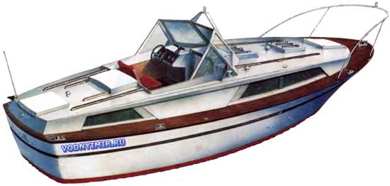
When developing the drawings of the Grinda, the task was to design a seaworthy and comfortable 10-seater boat, designed for sailing in the coastal zone of the seas and in large reservoirs, suitable also for long-distance tourism along main — navigable rivers. At the same time, it was necessary to take into account the numerous wishes of those readers who would like to find drawings of a boat designed for independent construction from reinforced cement.
| Basic data of the Grinda boat | |
|---|---|
| Longest length, m | 9,3 |
| KVL length, m | 8,0 |
| Maximum width, m | 3,0 |
| KVL width, m | 2,7 |
| Full side height, m: | |
| — in the nose | 2,0 |
| — amidships | 1,65 |
| — in the feed | 1,70 |
| Draft by KVL, m | 0,80 |
| Displacement by KVL, t | 8,60 |
| Recommended engine power, hp | 50-100 |
| Travel speed at engine power 60 hp, km/h | 16 |
General view of the boat
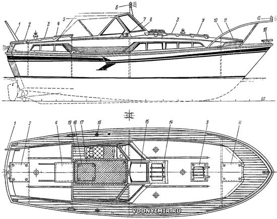
zoom in, 90.5 KB
1 — flagpole, L=800 mm; 5 — rear hatch; 3 — handrail; 4 — sliding hatch to enter the aft cabin; 5 — folding removable awning; 6 — top light; 7 — side distinctive light; 8 — windscreen; 9 — light hatch; 10 — bow railing; 11 — forelock; 12 — bow light-headlight; 13 — mooring duck; 14 — light hatch; 15 — «window» — opening part of the windshield; 16 — filling neck of the fuel tank; 17 — removable sheet for removing the engine; 18 — hatch to the engine compartment (option); 19 — locker seat.
The use of this material has led to a number of features of the project and in particular — the choice of the main dimensions and contours boats. It is known that even with the minimum technologically achievable thicknesses of reinforced cement structures, the hull of a small vessel turns out to be too heavy. Only when the length of the reinforced cement body is more than 9-10 m, its weight is comparable to the weight of steel or wood (of course, with equal structural strength). With a length of 9.3 m, the proportion of the hull weight in the displacement of the boat turns out to be quite significant: about 40%, i.e. about 6-8% more than in the manufacture of the same hull made of wood. In this case, this means that with engine capacities up to 100 hp available to amateur shipbuilders, it is almost impossible to bring such a boat to clean planing. It is necessary to count on displacement swimming with a relative speed Fr=0.4-0.6. It is for this speed range that the contours of the Grindy hull are designed.
Theoretical drawing of the «Grinda» armored cement boat
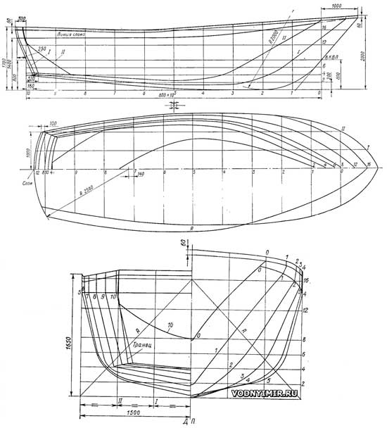
zoom in, 1500x1778, 222 KB
Coefficients of the theoretical drawing with a displacement of 8.6 tons: δ=0,5; β=0,74; α=0,78.
The position of the center of the magnitude is xwith = -0.38 m.
The body is made round-cheeked for most of its length, i.e. it has the shape most suitable for construction from reinforced cement. Convex curved surfaces of thin reinforced cement cladding under external loads work like an eggshell, the structure turns out to be rigid even with a relatively small number of reinforcing bars — frames and stringers. Only in the stern itself does a sharp cheekbone appear. A flat bottom in the stern with a smooth rise from the support is necessary to reduce the running trim that occurs when driving at speeds close to the upper limit for this hull. In addition, the additional waterline area is also useful for increasing the stability of the vessel.
It can be noted that the applied combination of displacement contours on the bow half of the hull and sharp-cheeked planing in the stern also allows the installation of an engine of significantly greater power — up to 250-300 hp. When driving in planing mode, the estimated speed is 16-18 knots.
In the bow of the hull, the outlines of the waterlines are optimal for design speeds — they are made straight with a moderate angle of sharpening at the stem; the sides in the surface part have a significant collapse here, ensuring good germination of this heavy hull on an oncoming wave. The side line is made with a longitudinal saddle characteristic of boats floating on a sea wave. In general, in the contours of the «Grinda» a lot is suggested by the experience of designing seaworthy raid boats and rescue service boats.
The hull is equipped with a stabilizer keel that moderates the side pitching and drift in a crosswind, protecting the propeller shaft and propeller from damage when stranded. Of course, it will be useful to provide the propeller with an annular profiled nozzle, which will not only improve the protection of the propeller, but also increase the efficiency of the propulsion (see, for example, here).
The low speed of the boat is unlikely to be regarded as a disadvantage by its crew: more than when sailing on the same «Progress», the time spent on the transition is more than compensated by high comfort. The captain of the Grinda will not need to hurry to get to any point just to equip the ship's safe parking and set up camp on the shore before dark: if necessary, you can go around the clock on the «Grinda», organizing night watches and at the same time providing normal rest for at least 7-8 crew members. Ultimately, much less dependence on weather conditions on the highway will also save time than with serial motors.
The project provides for a two-cabin layout with a medium engine arrangement, which is also used in the project of D. Bich (see here). This solution has a number of advantages. Firstly, the builder gets a certain freedom in choosing a mechanical installation: the weight of the engine practically does not affect the trim of the boat; it is possible to install, for example, a converted car engine with a gearbox, which will solve the difficult problem of the reverse gearbox. The best option, of course, is a diesel engine with a capacity of 20-60 hp with a direct reverse gearbox or the use of an adjustable pitch propeller. Secondly, when traveling for any length of time, it is always more convenient to have two living quarters than one. Thirdly, it is taken into account that during the transition in good weather, the entire crew usually gathers in the cockpit; with its usual aft location, this would inevitably lead to an increase in trim on the stern and a significant increase in water resistance to the movement of the boat, i.e. a drop in speed. The cockpit above the engine has a self-draining design: its bottom is located well above the waterline. The cockpit is quite spacious: its length is 2 m. On warm nights, you can arrange sleeping places here by laying inflatable mattresses and putting up an awning.
General location of the boat
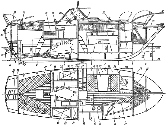
zoom in, 2329x1981, 160 KB
Positions 1-19 — see the drawing of the general view of the boat; 20 — emergency tiller; 21 — ventilation «fungus»; 22 — steering seat; 23 — control panel; 24 — forepeak; 25 — platform; 26 — cabinet; 27 — toilet; 28 — closed shelf; 29 — open shelf for the receiver; 30 — table; 31 — sofa; 32 — wardrobe; 33 — fuel tank; 34 — fuel compartment bulkhead; 35 — engine; 35 — exhaust pipe; 37 — bunk, locker at the bottom; 38 — shelf; 39 — tiller compartment; 40 — rechargeable battery; 41 — potable water tank; 42 — sink; 43 — shelves for dishes; 44 — gas stove; 45 — tubular suspended bunk.
In the bottom of the cockpit, it is necessary to provide a removable sheet of plywood or metal for the possibility of inspection and repair of the engine. Routine engine maintenance will be carried out through a manhole in the forward bulkhead of the engine compartment. The exhaust pipe is brought to the left side at the level of the running waterline. To prevent the engine from being flooded with water when rolling, it is necessary to make the exhaust pipe in the form of a steep knee with a bend to the level of the upper deck.
The aft cabin is equipped with two sofa beds; if necessary, you can also fix another suspended bunk here — you will get a third berth. There is enough space under the sofas and in the cupboards to accommodate personal belongings and supplies of the ship.
In the forward cabin, an asymmetrical arrangement of equipment with a dining area that can be transformed into a double bed is recommended: the table is lowered to the same level with the sofas, soft backs are placed on it. On board, you can arrange a galley with a gas stove and a sink, as well as stationary and suspended (tubular) bunks. At the forepeak bulkhead, it is worth equipping a toilet with a portable bucket or forced pumping of the toilet with seawater. The bulky cabinet at the bulkhead of the engine compartment is designed for the crew's shore clothing; waterproof bags and shoes can be stored in lockers under sofas. The cockpit is equipped with lockers for life jackets, mooring ends and fenders.
Fuel tanks with a total volume of 250-400 liters are best located in the area of the midship frame, on the sides of the engine compartment, separating them from the engine with light metal bulkheads with asbestos insulation. Reliable supply and exhaust ventilation of both the engine compartment and fuel tanks must be provided.
To lighten the weight of the hull, not only all bulkheads, but also the deck and the cabin should be made of wood using waterproof plywood. This will simultaneously simplify the installation of hatches, portholes and other equipment of the boat.
Now about the features of the construction of the actual reinforced cement building. The readers of the collection could get acquainted with reinforced cement as a type of reinforced concrete and the use of this material in amateur shipbuilding, as well as with some of the implemented projects of small reinforced cement vessels from publications in previously published issues (a list of the most important of them is given at the end of the article). The books of the Biryukovich brothers «Small vessels made of glass cement and reinforced cement» («Shipbuilding», 1965) and V. F. Bezukladov and others will be useful in this work. «Hulls of ships made of reinforced cement» («Shipbuilding», 1968).
Recall that the armocement consists of sand-cement concrete reinforced with several layers of wire steel mesh with a fine cell — usually no more than 3-12 mm. The mesh layers should be evenly distributed over the thickness of the reinforced cement structure to ensure dispersed reinforcement (i.e. «distributed», as opposed to concentrated reinforcement with thick rods in conventional reinforced concrete). For the preparation of the solution, fine sifted sand with grains with a diameter of no more than 2.5 mm is used (whereas for reinforced concrete, the size of the grains of sand does not matter; even gravel is used) and cement of high-strength grades. As a result, the reinforced cement structure turns out to be both sufficiently strong and sufficiently dense (waterproof) even with a relatively small wall thickness.
Usually on reinforced cement vessels up to 15 m long, the outer skin has a thickness of 15-20 mm. Its weight turns out to be close to the weight of a 3-4 mm thick steel skin, so it is natural that only such vessels are built of reinforced cement, as well as steel, for which the weight of the hull does not play a primary role — displacement boats, keel sailing yachts.
An important characteristic of the reinforcement cement is its saturation with reinforcing mesh. The coefficient of the specific surface of the mesh, characterizing the amount of metal (the total surface of the wire) per unit volume of the reinforcement, should be 2-3 cm²/cm³ the weight of the mesh per 1 m of the structure should be at least 400-500 kg. (© www.vodnyimir.ru). The thicker and more evenly the mesh layers are arranged along the thickness of the structure, the smaller the cell and the wire diameter of the mesh used, the higher the strength and elasticity of the reinforcement. At the same time, of course, we must not forget about the need for dense filling of the entire space between the reinforcing wires of the mesh with cement-sand mortar.
It should also be added that the reinforced cement differs from reinforced concrete by 5-7 times less thickness of the protective outer layer. A very thin (2-3 mm) outer layer works together with the entire thickness of the material during impacts, thereby preventing the destruction of the surface and the formation of cracks even under heavy bending loads.
The construction of the reinforced cement housing largely depends on the accepted method of construction. Three methods are used: construction without a form (formwork) — directly on a set of tubular or wooden frames exposed on the slipway; molding of an almost unassembled body on a punch (dummy) or in a matrix. In this case, for the construction of one vessel by an amateur, a non—decking method is recommended, which saves time (no need to make a punch or matrix) and provides high strength.
The metal frames remain in the thickness of the skin after the body is homologated. Accordingly, the disadvantage is the need to manufacture this very transverse set in the form of closed welded frames from tubes or reinforcing rods. It was this method that was chosen in 1943 by the inventor of the armament, Pierre Luigi Nervi, to build the world's first armament yacht «Irene»; in the future, the technological techniques he developed were used to build at least 500 armament vessels of various types and purposes.
The frames for the «Grinds» body can be bent from a half-inch (1/2") a water and gas pipeline pipe; the stem and keel are made of the same pipe. In total, 10 frames will need to be made, including the transom frame. All the frames are assembled right at the plaza breakdown. To stiffen the frames, the side ends of the frames at the deck level are connected with steel squares or pipes, which are removed immediately before the deck is installed. The lower ends of the frames are connected with welded temporary floras (you can leave them in the structure, but then you will have to bend them with each layer of the mesh laid along the keel).
Design diagram of the boat hull
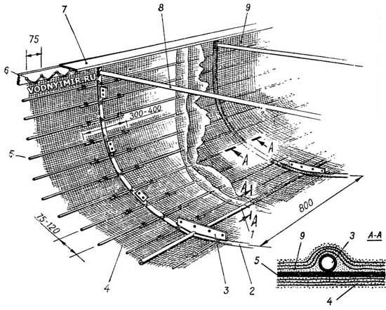
1 — keel; 2 — frame, pipe; 3 — knits (flor), δ=2-3 mm; 4 — mesh outside the set, 3 layers; 5 — stringer, Ø6 mm; 6 — knitting wire; 7 — square 4x50x50; 8 — temporary spacer, pipe; 9 — mesh on the inside of the set.
The hull is easiest to assemble in the usual position — keel down. (The molding of the body in the upward position with the keel is usually used when using a rigid punch, together with which the body is edged.) The frames are installed on the slipway in exact accordance with the theoretical drawing — after 800 mm. The upper ends of the side branches of the frames are welded to a steel square that forms a flange around the perimeter of the side for fixing the wooden deck. At the bottom — in DP — the frames are welded to the keel.
Armature design in the bow
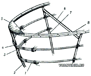
1 — stringer, Ø6 mm; 2 — knitting wire; 3 — stem, pipe; 4 — wire binding of the stringer to the stem; 5 — metal bracket; 6 — temporary spacer; 7 — frame; 8 — deck square.
On top of the exposed frames, stringers made of a 6 mm steel rod are laid. When this work is completed, a lattice surface of the housing is formed, ready to be covered with a reinforcing mesh. A woven steel mesh with a cell from 4 to 10 mm, manufactured according to GOST ZV26-47 from a wire with a diameter of 0.5-1 mm (mesh from No. 4 to No. 10) can be used. Three layers of mesh are laid on the outside of the set, carefully leveling it until a smooth and even outer surface is obtained, and three layers — on the inside of the case. The mesh of each layer is tied to the frames and stringers, and then the whole package is stitched through with a thin knitting wire.
The next stage of construction is the homologation of the housing with a solution, which includes: portland cement grade 500 — 100 wt. h., sand — 100-140 wt. h., water — 40-45 wt. h. To obtain a more plastic solution, it is desirable to add a plasticizer to the water for sealing — a sulfite-alcohol bard of one of the following grades: KBZH — 0.40 wt. h.; KBT — 0.25 wt. h. or KBP — 0.22 wt. h. (the amount of water in the case of the use of these additives can be reduced to 30 wt. h.).
Thus, the following basic materials will be required for the manufacture of the Grinda armo-cement case:
— steel water and gas pipes with an internal diameter of 1/2" (or 13-19 mm) — 90 linear meters (net weight — 115 kg);
— steel wire with a diameter of 6 mm — 520 p. m, weight — 120 kg;
— woven steel mesh No. 4-10 — 400 m², weight — 360 kg;
— knitting wire with a diameter of 2 mm — 2400 p. m, weight — 60 kg;
— a 50x50x4 mm square — 25 square meters, weight — 76 kg;
— portland cement grade 500 — 900 kg;
— river sand — 1200 kg.
In addition, you will need: a little sheet steel with a thickness of 2.5-3 mm, electrodes for welding fittings, steel squares, pipes, wooden bars and slats for loosening the set on the slipway.
Briefly about the features of the work at each stage of the construction of the vessel. As usual, you need to start with a breakdown on the plaza — plywood shield — the contours of the theoretical frames, as well as the outlines of the stem. Those who start such work for the first time can be recommended to familiarize themselves with the book «15 projects of vessels for amateur construction», published by «Shipbuilding» in 1974 and 1975 (this manual will be useful in the subsequent manufacture of the deck and equipment of the vessel).
Table of the «Grinda» boat's plaz ordinates
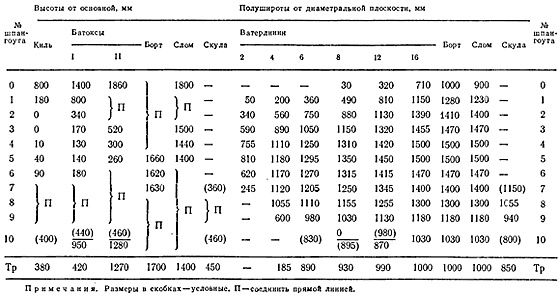
The ordinates in the table are indicated for the outer surface of the housing. This means that when splitting the frames, it is necessary to take into account the thickness of the outer skin, i.e. to set aside 15 mm evenly along the entire line from the resulting contours of the frames. It is recommended to start drawing frames on the plaza from the widest frame — from shp. 5. According to the table, the positions of the points are found on the grid lines — waterlines and buttocks, and then nails are hammered into the plaza at these points, which serve as supports for bending with a flexible rail when drawing a pattern outline of the frame. The frame line on the plaza should be smooth, freely enveloped by a wooden rail with a cross section of about 6x15 mm; the rail length of about 1.5 m is sufficient.
It is better to start the manufacture of frames from shp. 0 — the smallest and having a simple perish, and work sequentially in the stern. Each symmetrical pair of pipes should be immediately marked so that they cannot be confused later. For bending pipes, conventional tools can be used, widely used by plumbers or gas workers. If it is not possible to get them, you can make a simple tool from a tee designed to connect pipes half an inch larger in diameter than the diameter of the tubes used for the manufacture of frames.
Devices for bending tubular frames
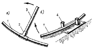
a — tee with lever handle; b — plate with welded stops. 1 — frame; 2 — tee; 3 — pipe-lever; 4 — pipe trim.
The tee is screwed onto a pipe that serves as a lever and has a sufficient length (from 1 to 1.5 m). When working, it is better to use two such devices, put on a bent frame. It is possible to control the bending of the frame branch by applying it to the plaza, on which, for convenience of work, nails should be filled along the frame line. In addition to the number, the position of the side line and waterline No. 8, which will serve as control lines during further assembly of the hull, should be marked on each frame (with a grain and paint).
Temporary crossbars from pipes or squares are grabbed, retreating 40-50 mm from the mark of the side line down. On each crossbar, as well as on the flora below, the position of the DP line is marked; having imposed the assembled frame on the plaza, the extra ends of the frame protruding above the side line are cut off.
The tubular stem is welded butt-to-butt with the keel. Previously, before assembling the body on the slipway, a reinforcement unit for the removal of the propeller shaft through the body of the deadwood pipe is also manufactured; naturally, before that, the builder must develop as detailed and large—scale sketch of the installation of the engine on the foundation and shaft line as possible (it's not bad even to make a mock-up of the plywood foundation, which will then be useful for direct «fitting» in the hull of the boat).
The next stage is the equipment of the slipway. The construction of the reinforced cement housing can be carried out under any canopy or even in the open air, but it is important to provide a solid foundation and a rigid base to control the correctness of the assembly. The basis can be a number of cross bars laid on the ground (such as sleepers), pieces of rails or large profile steel (I-beams, channels, etc.). On the slipway, it is necessary to punch the DP line along the entire length of the vessel using a stretched steel string. It is also important to establish the exact position of the main plane from which all vertical dimensions — heights — will be counted. For this purpose, it is convenient to dig vertical racks into the ground in the bow, stern and amidships and use the hose level to bring the position of the OL and waterline 8 to them. In the future, by attaching one of the hose level tubes to the desired mark, and the second to the verified structure on the slipway, you can control the heights.
The first to install a bookmark on the slipway is a keel with a stem and a stern with a deadwood pipe. Their position is verified by the plumb line and level, gaskets of the required height are installed under the keel. It is advisable to have a strip of three layers of mesh under the keel in advance, which will be used to reinforce the outer part of the skin. After the final fixing of the bookmark to the slipway, the frame frames are sequentially installed on the keel, starting from the bow or stern. When applying the hose level tubes to the marks on the frame and to the control marks on the slipway posts, the builder must make sure that the left and right marks are at the same height, coinciding with the position of the control mark. The verticality of the frame installation is checked by a plumb line. The frame frame is immediately attached to the keel by electric welding, the upper part is fixed by attaching temporary cross beams to a temporary longitudinal beam extending along the entire length of the vessel, or to various kinds of supports or scaffolding. Clamps bent from a steel strip along the diameter of the frame pipe and having bolt holes will be useful; with the help of such clamps, the frame can be easily attached to any metal or wooden beam.
Three thin and wide slats will be required for the final check of the exposed set; it is best if they are the entire length of the case. One of them is applied externally and temporarily attached to the hull at the level of the side line, the other — at the waterline level, the third — along the bottom (approximately along the line of the batox B2 or diagonal R of the theoretical drawing). The builder must make sure that the surface of each rail fits snugly to each frame frame, maintaining its natural, free bend. If there is a large gap between the rail and any frame, it means that some mistake was made either during the manufacture of the frame or when it was installed on the slipway. (Check again the distance between the planes of adjacent frames — it should be equal to the value of the spacer.) If the gap exceeds 6-8 mm and a slight movement — the slope of the frame does not give the desired result, it is better to remove the frame from the slipway and try to bend it or even replace it with another fitting in place.
With satisfactory smoothness of the contours, you can put the deck square in place, grabbing it to the upper ends of the frames with electric welding. In the vertical shelf of the square, it is desirable to drill holes in advance for knitting wire, which will attach the edges of the reinforcement mesh of the skin to it, and in the horizontal one — holes for the deck mounting bolts.
Now it's time to put a stringer on the body. It is advisable to use rigid and even bars that ensure a smooth surface of the housing. If soft wire is used, it must be carefully straightened. The rods are applied to the frames from the outside, starting from the stem. The bow end of the stringer is bent in the form of a hook, bending it around the stem pipe. At the same time, you should not bend the rod along a very small radius — cracks may appear in it, which will subsequently cause cracks in the reinforced cement cladding. The minimum radius when bending any parts of the reinforcement must be at least 6 diameters with a hard bar and 4 diameters with a soft one.
Boat projects for self-construction
Share this page in the social. networks or bookmark:
