
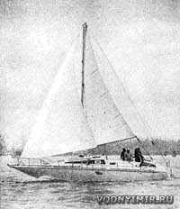
A 40-foot planing motor sailboat. High-speed motor-sailing gliding yacht
 A V-5 type motor sailboat glides at a speed of about 50 km/h. |
The idea of creating such a motor-sailing pleasure yacht that would be capable of planing while running under the engine has interested me for a long time, but I really started working on a draft design of such a vessel in 1972 (several articles illustrated with my sketches of this vessel appeared then in yacht magazines).
An Italian shipyard showed interest in the construction of a high-speed motor sailboat, but, unfortunately, the project was never implemented then. I was extremely disappointed, but there was nothing to do: this shipyard was undergoing a period of reorganization, my unusual sailboat did not fit into its program in any way.
Several years have passed. At the international exhibition of boats and yachts in Genoa in 1976, the owner of the Venetian shipyard «IAG Nautica SRL» Nani Sartorio became interested in my project and decided to get things moving. In June 1978, a planing motor sailboat with a hull made of glued wood and plywood was finally launched, and we began testing it. First of all, sea trials, because I was very concerned about how the ship would go to planing, how it would be controlled at full speed. Of course, I was also interested in what kind of maximum speed it would develop.
| Basic data of the planing motor yacht «V-5» | |
|---|---|
| The longest length/by KVL, m | 11,89/9,14 |
| Maximum width, m | 3,96 |
| Draft by hull/keel, m | 0,51/1,83 |
| Empty/full displacement, t | 6,2/7,5 |
| Engine power, hp | 2x240 |
| Speed under the engine, km/h: | |
| maximum | 54 |
| cruising | 44 |
| Sail area, m² | 49,5 |
| Cruising range under the engine, km/h | 510 |
| Fuel capacity, l | 700 |
| Fresh water supply, l | 250 |
 The general arrangement of the planing motor sailboat «V-5». |
The results of these first tests were the most encouraging. While we were testing the yacht under the engine, sheet winches and other equipment were mounted on its deck for the normal operation of sailing weapons, so after a couple of days we were able to go to sea to test the qualities of the yacht under sail.
 «V-5» goes well in the backwind. |
Alex Carozzo, a famous Italian solo yachtsman, commanded here. Although the winds were not strong, our yacht obeyed the rudder well and went easily even in the weakest breeze. Alex immediately felt that the yacht was well balanced and «predicted» that it would handle perfectly in a fresh wind. Such a wind blew a few days later. The yacht cheerfully cut through the waves. Alex was pleased, although, of course, it was difficult to estimate the speed of the yacht as accurately as we measured it with the help of instruments when sailing under the engine!
Anyway, we tested our vessel both under the engine and under sail, and were very satisfied with the practical embodiment of the compromise that any attempt to combine many such contradictory requirements and conditions inevitably presents.
 Under the spinnaker on the backstay course. |
The ultimate goal of my work was to create a simple and practical a motor sailboat capable of sailing normally on all courses relative to the wind and planing outside the «hump» area of the drag curve at a speed that would correspond to the long-term (cruising) power of the engines.
The complexity of the project intrigued me extremely. It was a real struggle with many technical problems that had to be overcome in the simplest way. Usually, the designer has at his disposal a large amount of information on previously built vessels; this helps him to develop a good project for a sailing yacht or a motor boat of a traditional type. Having withstood the parameters determined by statistics and their ratios (the ratio of engine power to the weight of the vessel, the static load coefficient, mass distribution, etc. P.), he will receive a new vessel with predetermined qualities. The complexity of design increases disproportionately when trying to create something new — in an area where there is neither a satisfactory prototype precedent nor any statistics.
By combining the two types of vessels, I was essentially developing a new type of vessel. Many aspects of the project were particularly difficult due to the opposite approach to their solution. I will name four such problems:
Body contours. When sailing, the speed is much lower than when planing under the engine. However, for each of these two speeds, completely different body contours will be optimal.
Stability. While any sailing vessel needs to ensure high transverse stability (by giving the hull a special shape and ballasting), the typical sharp-cheeked hull of a speedboat turns out to be felled and not stable enough to carry sails on it; at the same time, any ballast will be a detriment to speed when running under the motor.
Resistance of protruding parts. The developed fin of the keel to counteract drift and the rudder, the small diameter of the propeller are desirable to achieve good sailing qualities under sail, while for planing under the engine, on the contrary, it is desirable to have no fin at all.
The mast. To equip a yacht with effective sails, a high mast is necessary, while when running under the engine, streamlined forms of superstructures are needed, and the mast creates excessive (and significant) air resistance.
 Side view and layout of the motor sailboat «V-5». |
I assumed that I would fit into the design length of the hull, equal to 35 feet, but when I started developing the drawings, it turned out that the rooms needed by the customer: two separate cabins (for two couples) plus a spare cabin with two bunks for guests, a toilet, a galley, a dining area, etc., can accommodate only with a length of the vessel is somewhere around 40 feet. I chose the general layout of the yacht with a central cockpit and a separate aft cabin, as this made it possible to conveniently place the engines under the cockpit deck — in the middle part of the length of the yacht.
My colleague Franco Harrauer was responsible for the detailed layout of the premises, but I had to make sure that the correct alignment was ensured, i.e. that the main components of the weight (engines, fuel supply, etc.) were correctly positioned in terms of ensuring the desired position of the overall center of gravity of the vessel.
As a power plant, I chose a pair of Fiat S.R.Z. diesels, taking into account the fact that these engines give a total long-term power of about 400 hp and provide good speed above the critical «hump» on the ship's resistance curve. Generally speaking, according to my calculations, 300 forces would be enough to bring the yacht to planing, but at the same time there would be too little power reserve in case of overcoming factors such as overload, fouling of the bottom, a small loss of power, etc.
In order for the same hull to be able to meet two completely different requirements as much as possible, corresponding to the operating speed ranges, say, 8 knots when sailing and 30 knots when planing under engines, I developed compromise contours with a changing geometry of the bottom and a sharp cheekbone. The lines of the keel and cheekbones at the extremities rise up to the waterline, as usual on the hulls of sailing yachts. However, the middle part of the hull has typical boat planing contours deep V; this part of the hull ends in the stern with a low transverse redan. Two large controllable plates (one on each side of the keel) are attached to this redan on hinges, which, when lowered, serve as a continuation of both planing surfaces of the bottom, and when sailing, they rise and press against the hull, smoothly fitting into the displacement yacht contours; now water flows smoothly flow around the hull without turbulence and disruption of the flow on the the aft edge of the plates.
As already noted, unlike a boat, a yacht needs additional stability to carry sails. This is usually achieved by using ballast or special hull contours, or a combination of both methods. It is quite obvious that in this case it was impossible to use solid ballast (lead, cast iron); this dead weight would worsen the speed qualities of the vessel when running under the engine. To ensure overcoming the «hump» of resistance and access to planing, it would have been necessary to install even more powerful engines, provide a larger fuel supply for them, and all this would lead to an increase in the weight of the vessel and the need for further increase in power, etc.
 «V-5» at a cruising speed of about 45 km/h. |
Therefore, a more «economical» way of ensuring stability was chosen due to the contours of the hull, and I used somewhat unusual cross-sections along the frames. As is known, flat-bottomed hulls have the maximum transverse stability, however, at high speeds in open water, such a hull experiences huge overloads — it can easily be broken when hitting waves. Most modern high-speed boats have bottom contours with a keel of more than 20°, but such hulls turn out to be too loose under sail. I compromised by designing planing surfaces in the stern with a keeling angle of 33°; this part of the hull with deep V contours in cross section occupies about 2/3 of the width of the bottom. At the cheekbone, these planing surfaces smoothly turn into almost horizontal flat areas. Thanks to this, it was possible to obtain a soft, comfortable course of the vessel on a wave and at the same time provide the required initial transverse stability.
Additional stability at large roll angles contributes to a significant collapse of the sides outwards.
Finally, the reception of ballast water (weighing about 1 ton) into the built-in tanks located in the inter-bottom space under the cabin floor is also provided. These tanks are filled in necessary cases — when sailing or under the motor, but at low speed — and are emptied automatically when the vessel goes planing.
It is clear that the fin keel on the motor sailboat had to be made retractable into the hull, otherwise it would significantly increase the water resistance and make it difficult to reach the planing. The steering wheel presented a similar problem. I tried to use a partially rising steering wheel, but later, to simplify the design, I left it constant, but made the steering wheel pen taper to the bottom. Due to the almost triangular shape of the feather, its wetted surface automatically decreases significantly as soon as the vessel begins to rise from the water and switch to planing mode. When sailing at low speed, the wide upper part of the rudder pen represents an additional area necessary to ensure controllability.
Two propellers with a diameter of 430 mm each would create considerable resistance when sailing. To reduce their resistance as much as possible, I hid the screws in the wells arranged in the aft part of the hull, where the water flow rate is somewhat lower. So it turned out that these screws began to work similarly to the surface (semi-submerged) propellers of high-speed boats. As a result, the inclination of the propeller shafts also decreased, which also somewhat reduced the water resistance when they flow around.
In these circumstances, the use of semi-submerged screws was the best solution, since such screws have a large pitch and a small blade area, which favorably affects the reduction of water resistance to the movement of the yacht under sail.
Perhaps the most obvious compromise of this «made up of compromises» project was the sailing armament. High and narrow sails give the greatest thrust per unit area, but in this case I chose a rigging with a low mast. This is done for a number of reasons. A tall mast would be very vulnerable when planing on waves: its vibration would progressively increase with height with a corresponding increase in stresses in the mast itself and in the standing rigging. Secondly, it was desirable to place the center of sail as low as possible: this reduced the heeling moment, simplified the most difficult problem of ensuring stability and made sailing more comfortable. It was also important because the owners of such yachts in most cases will be former boaters, not real yachtsmen.
Finally, I used every opportunity to reduce air drag to a minimum, given its significant negative impact on the maximum speed of the vessel. In addition to the aerodynamic resistance of the developed mast to movement, it is necessary to take into account the water resistance when the rudder deflects, which is necessary to keep a vessel with a developed mast on course.
 A variant of a sailing rig with a hang glider sail. |
Sea trials showed that our efforts were rewarded: the maximum speed under the engines was 32.5 knots, long cruising — 25 knots.
We are currently working on a project for a more efficient sailing armament with a greater elongation of the sails, and Franco Harrauer is developing an original sail like a hang glider. If the practical details of such a sail are worked out, the vessel will receive many significant advantages (such as, for example, the absence of a high mast with all the disadvantages associated with its presence on a motor boat).
Now the shipyard is planning to release a small batch of motor-sailing vessels built according to the same project, but with fiberglass hulls.
Renato Levi, Italian designer, 1978.
In the section «Motorboats, boats, yachts — miscellaneous, reviews, tips»
Share this page in the social. networks or bookmark: