Protection of the propeller by a tunnel
E. N. Rivkind, «Propeller tunnel protection»
For the first time, tunnel formations of the bottom began to be used on shallow-seated river steamers: an increase in the size of ships and an increase in engine power led to the need to use large-diameter propellers, therefore, in order to maintain a minimum overall draft, it was necessary to place the screw in a special recess (tunnel) in the bottom. Before we talk about the specifics of using the tunnel as a means of protecting the propeller on boats, we will give some general recommendations developed by the experience of operating tunnel vessels on river transport.
Usually, the upper edge of the disk of the propeller working in the tunnel is near or even slightly above the waterline, however, when the screw rotates in front of it, a vacuum is created, thanks to which the water, rising, fills the entire space of the tunnel (this is also facilitated by a decrease in pressure in the tunnel when the ship moves).
«Lifting» the axis of the screw, it is necessary to keep in mind two circumstances. Firstly, in order to exclude the possibility of air breaking through to the screw in reverse, the aft edge of the tunnel arch should be located below the cargo waterline. Secondly, it should not be forgotten that with the rise of the screw axis, the efficiency of the entire propulsion complex will fall, since additional energy will be required to lift the water.
When the gap between the edge of the screw and the arch of the tunnel is made small — less than 0.06 of the diameter of the screw, the efficiency of the propeller itself increases due to a decrease in end losses on the blades passing under the arch. But, on the other hand, reducing this gap leads to additional vibration due to the difference in forces on the blades located at the top — at the arch and at the bottom. On relatively slow-moving vessels, this phenomenon is combated by installing a «half-nozzle» — a profiled half-ring covering the propeller from below. On planing boats and boats moving in transition mode, the gap between the screw and the tunnel arch has to be made even more optimal in terms of increasing the efficiency of the propulsion (Δ=0.15-0.20 Db), since with a high number of revolutions of the screw, usual on such vessels, vibration is especially dangerous, and the installation of a half-nozzle that provides great resistance to movement is impractical, since it negates all possible gains in efficiency.
The location of the propeller in the tunnel can be considered as intermediate between the «classic» open version and the fully protected impeller of the water jet propulsion. In comparison with water-jet, tunnel boats have a number of advantages. First of all, the efficiency of the propeller working in the tunnel is 10-20% higher than the wheels of the water cannon. It is easier to make a tunnel on the bottom than to make and mount a water intake and a water cannon pipe. Reverse gear on a tunnel boat is provided by the installation of a standard reverse gear, and for a water cannon it is necessary to make a special hydraulic reversing device. A large-diameter propeller (and such screws are placed on relatively slow-moving boats, for which the size of the stop is especially important) is easier to place in a tunnel than in a water cannon pipe.
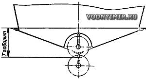 Changing the overall draft and protecting the propeller when installing the tunnel. |
In comparison with the open location of the propeller, the use of a tunnel allows you to reduce the overall draft, i.e. increase the patency of the boat, and provide more reliable protection of the propeller by the hull of the vessel. The propeller shaft can be installed with a smaller angle of inclination relative to the main plane, which somewhat improves the working conditions of the screw. On planing boats, the bending of the tunnel arch down at the transom, which creates a hydrodynamic differentiating moment on the bow, allows for more aft centering. However, the speed of a tunnel boat will always be slightly lower than that of a similar boat with an open propeller. The fact is that the resistance to movement of a boat with a tunnel is usually 10-15% greater than boats without a tunnel. Why is this happening? In the area of the tunnel, the speed increases and the direction of the water flow flowing around the hull changes; at the same time, the pressure in the stern decreases, and as a result, an additional water resistance force appears (the resistance of the tunnel shape). In addition, the wetted surface of the tunnel is always larger than the flat bottom in the same area, which leads to an inevitable increase in friction resistance.
Example of a theoretical drawing of a wide tunnel
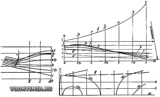
a is the arch of the tunnel in DP; b is the curve of change in the values of the interface radius r; c is the theoretical line of the tunnel edge; d is the contour of the keel line without a tunnel.
On planing boats, the effect of another factor is added: the projection area of the tunnel on the bottom is, as it were, excluded from the area of the carrier — planing plate (this can significantly reduce the hydrodynamic quality of a seemingly optimally designed boat).
Example of a theoretical drawing of a high-speed boat tunnel
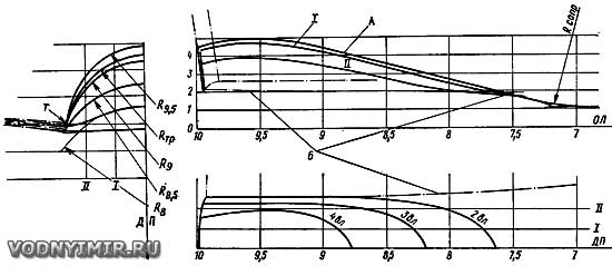
A — the longitudinal line of the tunnel; B — the line of intersection of the frames of the tunnel and the body.
It should also be borne in mind that due to the greater steepness of the contours (along the buttocks), an additional vacuum arises in front of the propeller in the tunnel — the suction force, which is spent on overcoming an additional part of the propeller stop (for tunnels recommended in this article — about 3% of the stop). Finally, it is more difficult to make a tunnel bottom than a flat one.
And, nevertheless, tunnel contours are used, and at the same time not only in the design of boats with a small overall draft. For example, thanks to the ability to move the engine on a tunnel boat closer to the stern (taking into account the small inclination of the propeller shaft and its position in height), it is possible to better use the useful volumes of the interior, reduce noise in the forward cabin. An example of the application of the scheme under consideration can be the water-jet boat «Stork» (see No. 30 of the collection «Boats and yachts»).
The contours of the boat tunnel are determined by the following main factors: the location of the engine relative to the tunnel; the location of the propeller and its diameter; the limited draft of the boat; the presence, location and shape of rudders, nozzles or half-nozzles; the relative speed of the boat.
An example of a rather complex contours with lifting the bottom and water supply to the screw along two arches converging in the stern
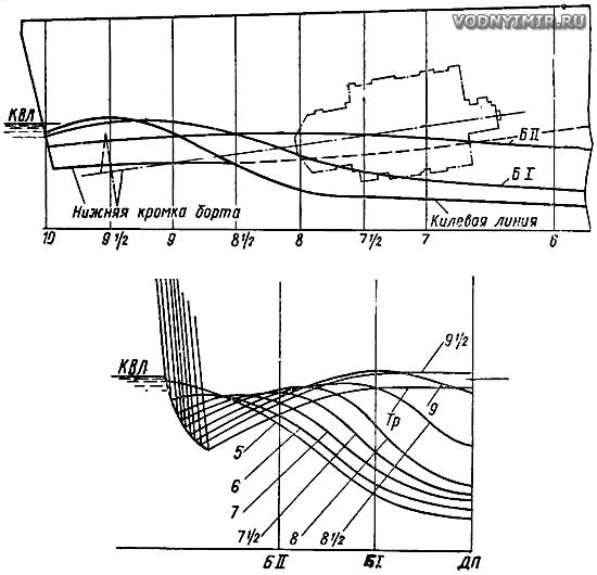
The farther the engine is located from the transom, the smoother the water flow to the propeller can be made, which has a positive effect on the operation of the screw and reduces the water resistance to movement. If the engine is located too close to the transom, the rise of the buttocks becomes very steep, which is highly undesirable. In the case of a constructive need for such an arrangement of the engine to reduce losses, it is recommended to perform the tunnel as if obtained by connecting two «nose» tunnels converging to the DP (an example of such a rather complex bottom profiling is shown in one of the sketches given). With a relatively small hull width compared to Dv, a flat aft part of the bottom with rounded bends of the cheekbones lowered below the KVL can be made on slow-moving boats. The position of the propeller along the length of the boat determines the contours of the tunnel in section according to DP; the height of the tunnel is rigidly determined by the specified draft of the boat and the diameter of the propeller.
The aft part of the hull must have a shape that protects the screw from air suction (the lower edges of the sides must necessarily cross the surface of the water). The width of the tunnel depends mainly on the presence of handlebars, nozzles or semi-nozzles in it. A wide tunnel is necessary if, for example, two rudders are located parallel behind the propeller; it can be made with side walls inclined to the DP, which smoothly turn into a vault at the top. When using a half-nozzle, the width of the tunnel practically becomes equal to the diameter of the screw. When placing one rudder directly behind the propeller, the tunnel width is 1.3-1.4 Db. In the case of using a rotary nozzle (which on a slow-moving boat gives an increase in the efficiency of the propeller), an average tunnel width of 1.6-1.8 Db can be assumed; such a wide cross-section improves the flow of water to the nozzle and provides the possibility of turning it.
The relative speed of the boat affects the nature of the flow around the aft part of its bottom. At lower speeds, it is permissible to design a tunnel short and with steeper buttocks; high-speed planing boats in such a short tunnel will experience flow disruption and insufficient filling of the tunnel with water.
A few recommendations for the construction of a theoretical drawing.
 Basic parameters of a typical tunnel. |
Let's turn to the diagram of the main parameters of the tunnel. The uppermost point of tunnel A is located at the place where the propeller is installed; it can rise above the KVL by no more than 5-10% of the boat's draft. The point of intersection of the tunnel arch line in DP with the keel line (point B in the diagram) should preferably be carried forward from the screw disk; at 5 heights of the tunnel Nt. The point of intersection of the tunnel arch line in the DP with the transom (point C) is usually located below the KVL by 3-5% of the boat's draft. Draw the curve smoothly along these three points, avoiding sharp bends and breaks. In this case, the tangent drawn at the top point of the tunnel arch (above the propeller blade) must be parallel to the shaft line. The coupling of the curve with the keel line is done along a sufficiently large radius to obtain a smooth flow entrance into the tunnel. The value of the radius R should be taken within 0.8-1.0 Lt.

Basic parameters of a typical tunnel.
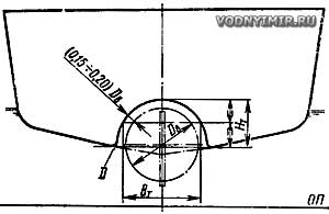
The transverse shape of the tunnel is determined, first of all, by the cross-section in the plane of the propeller location. In the most common variant, when there is one rudder in the DP behind the propeller of a gliding boat or a boat designed for transient movement, it is advisable to have a cylindrical cross section with a gap between the tunnel arch and the edge of the blade in the range of 0.15-0.20 Db. At the same time, it is necessary to make sure that the shape and position of the steering wheel allow you to shift it on board within the transverse dimension of the tunnel. In the case of using a half-nozzle, the gap between the tunnel surface and the propeller blade can be reduced to 0.02-0.06 Lv.
In the theoretical drawing of a tunnel boat, the characteristic line is the intersection of the tunnel surface with the hull lining (line D). This line should be considered as theoretical, since sharp edges are unacceptable here. Rounding must be performed along a radius varying from 0.8-1.0 W in the nose of the tunnel to 0.02-0.04 W on the transom.
In the plan, the D lines should run parallel to the DP or diverge to the nose by no more than 5% of their length.
The tunnel can be made together with the housing or in the form of a separate structural element with its subsequent installation on the housing. On metal boats, the tunnel lining is usually stamped cold or hammered out on a punch (dummy) in a hot state. On boats with rack-and-pinion or plywood sheathing, the tunnel is easiest to make separately and from another material — fiberglass. A punch for forming a fiberglass tunnel can be made, for example, from foam. It is necessary to provide landings for the paw of the propeller shaft bracket and the rudder flange. The tunnel is attached to the casing with bolts or screws through the flange.
Tunnel formations of fiberglass, glass-cement and reinforced cement boats are obtained during the molding of the hull.
In the section «Motorboats, boats, yachts — miscellaneous, reviews, tips»
Share this page in the social. networks or bookmark:
