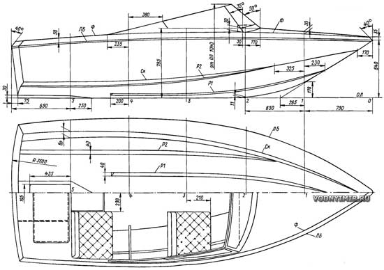
The project of the water-jet boat «Moray»
| Basic data of the boat «Moray» | |
|---|---|
| Longest length, m | 4,00 |
| Maximum width, m | 1,65 |
| Width along the cheekbone at the transom, m | 1,30 |
| Side height amidships, m | 0,67 |
| Empty weight, kg | 160 |
| Engine power, hp | 30-70 |
| Maximum speed with the engine from PM Vortex 30, km/h | 40 |
The interest shown by amateur shipbuilders in water-jet boats is not accidental. In our conditions, such boats have tangible advantages over boats equipped with a screw drive, or motor boats with outboard motors.
First of all, it is the high cross-country ability of water-jet vessels, making many shallow rivers accessible, simplifying the approach to an unequipped shore and parking the boat on the water. The rotor of the jet propulsion is better protected from damage when hitting underwater obstacles or floating objects, as a result of which propellers are most often deprived of blades. A water jet propulsion equipped with a hydraulic reversing device is much easier to manufacture on its own than an angular rotary-folding column or a reverse gearbox. Powerful and economical engines, «heads» of outboard motors, engines from motorcycles can be paired with a water cannon.
It is necessary, however, to immediately make a reservation that the water cannon does not have any advantages in speed compared to screw boats. On the contrary, the additional resistance of the water washing the intake, its rise (even to a small height) for release in the surface part of the hull of the boat cause a slight decrease in the speed of water-jet vessels. This decrease can be very significant if the propulsion is carelessly manufactured and used on ships that are not suitable for this chain. Experience shows that the best results can be obtained when using a water cannon on light planing boats equipped with a sufficiently powerful engine.
These considerations were taken into account when preparing the next boat project for independent construction. The proposed option provides for the installation on the «Moray» of an engine from a 30-horsepower «Vortex» with a standard gearbox, but without the deadwood part, suspension and hood. It will be necessary to make a light foundation based on the longitudinal beams of the hull set, to mount cooling and exhaust systems and, of course, to make a water jet propulsion.
Instead of the PM engine, you can install any other, similar in basic characteristics — power, mass, speed and dimensions. The engine from the «Moskvich» car for the proposed boats will be a little too big; in this case, it is better to lengthen the hull to 4.75-5 m.
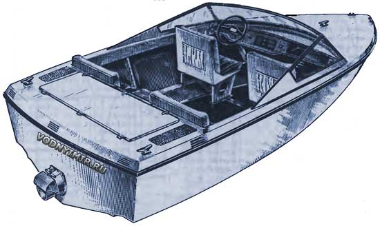
General location of the water jet boat «Moray»
The wishes of many readers have been fulfilled: the design of the case provides for its construction from fiberglass or composite construction — from plastic on a wooden set. The latter method is convenient for individual construction, since it is not required to produce a rather labor-intensive tooling — a punch and matrices, which are then discarded.
It is not excluded the manufacture of the body and the entire wooden structure. In this case, we refer the reader to the third edition of the book «15 projects of ships for amateur construction» («Shipbuilding», 1985), which describes in sufficient detail the techniques of the main works and according to which it is possible to select sections of all the connections of the set, using a project similar in size. To facilitate the lining of the sides in the bow, which have a concavity, you can use strips of plywood 150-200 mm wide, laying them diagonally at an angle of 45° to the rest beam necessarily in two layers. Then the skin is glued with two layers of fiberglass on an epoxy binder.
A few words about the contours of the boat. They are typical for modern planing vessels operated on rivers with a wave height of up to 0.75 m. Due to the moderate keeling of the bottom (17° at the transom), overloads during the course of the wave are small. Wide zygomatic splashers and longitudinal redans allow to slightly increase the hydrodynamic quality and reduce the amount of splashes escaping from under the bottom. The high freeboard and the large width of the hull along the deck ensure the safety of sailing on a wave of the specified height and the convenience of accommodating four people in a relatively small boat.
Theoretical drawing of a water jet boat
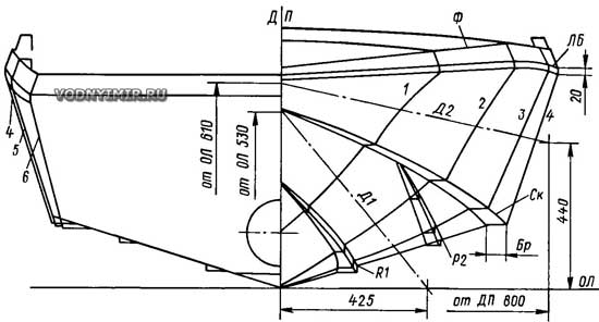
| Table of ordinates of the theoretical drawing, mm | ||||||
|---|---|---|---|---|---|---|
| Theoretical drawing line | Frame numbers | |||||
| 1 | 2 | 3 | 4 | 5 | 6 | |
| Heights from OL, mm | ||||||
| Bulwark — F | 710 | 730 | 730 | 714 | 676 | 635 |
| Side line — LB | 657 | 676 | 673 | 653 | 625 | 585 |
| Skula — SK | 418 | 310 | 235 | 195 | 182 | 182 |
| Half-width from DP, mm | ||||||
| Bulwark — F | 445 | 667 | 775 | 802 | 788 | 774 |
| Side line — LB | 465 | 690 | 800 | 829 | 810 | 760 |
| Skula — SK | 276 | 490 | 622 | 680 | 686 | 660 |
| Diagonal — D2 | 363 | 592 | 725 | 775 | — | — |
| Diagonal — D1 | 260 | 440 | 525 | 557 | — | — |
| Redan — R2 | — | 410 | 462 | 475 | 475 | 475 |
| Redan — P1 | 76 | 190 | 220 | 230 | — | — |
| The width of the splash guard on the cheekbone — Br | 28 | 48 | 57 | 62 | 70 | 75 |
Theoretical drawing (up to the inner surface) of the water intake
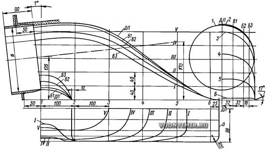
The diameter of the stator is 190 mm.
| Water intake ordinate table | |||||
|---|---|---|---|---|---|
| Cross sections | Half-latitude along the waterlines from the DP | ||||
| I | II | III | IV | V | |
| 1 | 45 | 95 | 95 | 88 | 57 |
| 2 | 97 | 97 | 96 | 91 | 64 |
| 3 | 97 | 95 | 95 | 79 | 0 |
| 4 | 97 | 92 | 59 | — | — |
| 5 | 84 | — | — | — | — |
| Cross sections | Heights by buttocks from OVL | ||||
| dp | B1 | B2 | B3 | ||
| 1 | 220/28 | 214/35 | 195/43 | 176/71 | |
| 2 | 224 | 218 | 196 | 180 | |
| 3 | 200 | 194 | 175 | 156 | |
| 4 | 134 | 129 | 116 | 100 | |
| 5 | 60 | 59 | 54 | 44 | |
If a composite structure is adopted, then the manufacture of the housing should begin with the preparation of frames and elements of the longitudinal set. The main role of lightweight frames is to give the body its shape. They can be cut from 8-12 mm plywood by gluing individual strips on the mustache in the area of the cheekbones. You can also use thinner plywood, using it for veneering on both sides of frames assembled from 7-8 mm planks. Less often, amateurs assemble frames from solid foam up to 30 mm thick, pasting them after molding the cladding with several layers of fiberglass.
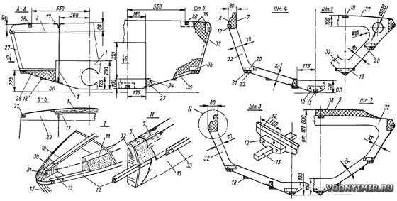
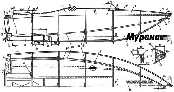
The design of the housing of the composite version, manufactured without matrices
zoom in, 1500x1023, 222 KB
1 — transom reinforcement, 25x280x700, pine; 2 — foam deck decorator at the transom; 3 — shelf, 8x150x1560, plywood or pine; 4 — engine compartment deck with flanging coamings for the hatch cover, δ=3,5; 5 — longitudinal bulkhead, fiberglass δ=1.5; 6 — bulkhead of the engine compartment (shp. 5) of three—layer construction - foam plastic δ=20 with pasting with two layers of fiberglass on both sides; 7 — pasting of the cockpit coaming, δ=1,5; 8 — coaming filler, foam; 9 — ledge decorator under the windshield; 10 — deck stringer, 10x20; 11 — deck edge decorator in the bow, styrofoam; 12 — break beam, 12x30; 13 — brashtuk δ=20; pine; 14 — brashtuk zygomatic stringers, δ=6-8, plywood; 15 — stem and keel, 22x30, glued together from two or three slats; 16 — outer skin, δ=3 mm — side, δ=4 mm — bottom; 17 — «wet square»; 18 — longitudinal redan; 19 — shorty 20x75x120 for fixing the keel to the frames; 20 — shorty 20x30x70 for fixing the zygomatic stringer; 21 — zygomatic stringer, 12x20; 22 — a rail along the width of the splash guard (a split is placed between the frames); 23 — flor; styrofoam decorator δ=20; paste over with 3 layers of fiberglass; 24 — sticker on the keel; 25 — longitudinal beam of the foundation under the engine — support of payoles; foam δ=30, paste over with fiberglass in 4-5 layers under the engine and 2 layers in the area of 4-2 shp.; 26 — foam; 27 — rail 25x30, cut into children. 3 and 29; 28 — rail 12x20; 29 — shelf 8x140x380; 30 — foam; 31 — stringer mounting rack 10 to the bracket 13; 32 — frames, plywood δ=8-10; 33 — collar 20x16, oak, ash; 34 — foundation gluing; 35 — rail 20x20, paste along the edges of the bulkhead; 36 — bar δ=20 for fixing the slats of the longitudinal set; paste into the bulkhead; 37 — the bow of the deck, δ=3,5; 38 — gluing the ledge under the glass, δ=1,5.
Cross sections on frames and nodes
The frames must be made to the full height of the sides together with the deck sections or beams. On the plaza, you should immediately mark the shergen-line, using which temporary slats are attached to the frames. Then the frames and the stem with the keel, glued in advance according to a template of two slats, are installed on a slipway consisting of two parallel boards. The hull will be built in an upward keel position, as well as boats of wooden construction.
Some difficulty may be caused by the manufacture of a convex transom. Its shape is set by two shelves 3 and 29, the trailing edge of which is processed along the radius. A sheet decorator is attached to them — fiberglass or thin plywood, then bars for the design of the edges of the bottom and sides. The convex transom improves the appearance of the boat, but if you sacrifice this, you can make it flat.
When the frames, transom and keel with stem are installed and aligned on the slipway, the rails of the rest bars and zygomatic stringers are embedded in the frames. It can be noticed that their cross-section is much smaller than that of wooden boats — just like the frames, the longitudinal slats serve only for the design of the hull contours. The required width of the zygomatic splashbox is obtained by gluing short slats or pieces of foam between the frames to the stringer. At the same stage, foam decorators of the longitudinal beams of the engine foundation are inserted on the bottom between the frames, which are subsequently pasted with fiberglass. The distance between the beams must be coordinated with the under-engine frame or brackets for mounting the engine.
Applying a piece of plywood to the slats of the exposed set, the film is removed from their edges, then the set is covered with sheets of fiberglass with a thickness of 1.1-2 mm. If it is not possible to get this material, then the sheets can be made independently using fiberglass and binder prepared for molding the case. The process is described by L. Nefedov (see here).
Sheets of the required sizes are glued on a table, necessarily installed outdoors. Tracing paper or cellophane or polyethylene, serving as a separating layer, is spread out on the table. 3-5 layers of fiberglass are applied to it, on which an epoxy binder is evenly applied with a plasticizer and hardener introduced into it, and the package is ironed with a heated iron. Due to the fact that the viscosity of the heated resin decreases, the binder impregnates all layers of fiberglass well. In those places where the binder was not enough, you can apply an additional portion of it and iron it again. After 20-30 minutes, a partial polymerization process occurs, in which a sheet of plastic acquires a certain rigidity, but it can still be cut with a shoemaker's knife and small shoemaker nails can be punched through it.
When ironing the iron, it is necessary to periodically clean the resin sticking to it with a sharp knife, and also make sure that the iron does not linger in one place. The heated area can be firmly glued to the iron and the plastic billet will be damaged.
| Optimal binder formulation (component content, % by weight) |
|||||
|---|---|---|---|---|---|
| 1 | 2 | 3 | |||
| Resin MON-1 or MON-3 | 89 | Resin NPS-609-21M | 85 | Resin ED-5 | 75 |
| Isopropylbenzene hydroperoxide (hyperiz) | 3 | Hyperiz | 4 | Dibutyl Phthalate | 15 |
| NC accelerator (Cobalt naphthenate) | 8 | NC Accelerator | 10 | Polyethylene Polyamine | 10 |
| Accelerator T | 1 | ||||
From the place of the case, which is supposed to be closed with a sheet of plastic, a template made of cardboard or thick paper is removed, cut along the contour and superimposed on the blank for marking. The edges of the parts of the set, which will be adjacent to the sheet, are lubricated with a binder, then the workpiece is put in place and attached to the frames and rails of the longitudinal set with small nails. If a sheet of plastic sags under its own weight, you should continue the process of polymerization of the binder — hang the sheet in the sun or use reflectors for heating. At the same time, it is necessary to check that the workpiece does not become so rigid that the plastic cannot be pierced with a nail or bent sheet along the contours of the body. If a ready-made fiberglass is used, it will have to drill holes for nails.
Thus, the entire surface of the case is closed. Joints and grooves of individual sheets should preferably be performed on the edges of the set. All the irregularities of the cladding are putty with epoxy putty, joints and grooves are glued with fiberglass tapes in 2-3 layers.
After exposure for two to three days, the plastic acquires sufficient hardness to sand its surface and proceed to gluing the entire body with additional layers of fiberglass to the desired thickness (on the bottom 4-4.5 mm, on the sides 3-3.5 mm). When laying the last layer of fiberglass, a coloring pigment can be added to the binder or the boat can be painted with pentaphthalic enamels after construction.
Using this technology, it is possible to manufacture in advance a three-layer shp. 5 bulkhead with a foam filler between the outer layers of fiberglass, as well as longitudinal fences in the engine compartment separating the fuel tanks and the battery from the engine.
Special attention is required for the formation of longitudinal redans. It is best, after gluing the body with two or three layers of fiberglass, to paste on the bottom of the billet of redans made of solid foam (in extreme cases made of wood) and glue them in 2-3 layers with fiberglass tapes so that the edges of the tapes go to the bottom by 25-40 mm. The subsequent layers of fiberglass on the bottom should be laid in the form of narrow strips between the redans.
The keel and stem, the transom transition points in the bottom and sides are recommended to be reinforced with additional layers of fabric.
After the hull is released from the slipway, it is turned over and the deck is designed. This is done by gluing foam bars between the frames. After polymerization of the glue, the parts of the foam that protrude beyond the edges of the frames are cut off, the foam is treated with a plane or a «grater» (a sheet of tin with holes punched in it with a nail with burrs), then with a rough skin. In the bow and stern, slats are embedded in the beams, which will support sheets of fiberglass when gluing layers of fiberglass on them.
Covering the aft and forward parts of the deck with fiberglass, a hatch cutout is made out of wooden slats in the stern. On the edges of these slats, lubricated with a separating layer (for example, vaseline or mastic for the floor), the edges of the fiberglass are bent, forming the coaming of the hatch cutout; after the plastic is cured, the slats are removed, and an appropriate cutout is made in the fiberglass. Foam is glued to the deck in the nose to form a projection for fixing the windshield. Then additional layers of fiberglass are molded onto the deck (it is enough to stick 2-3 layers on the foam decorators of its side sections).
A few words about the materials for the manufacture of the «Moray» hull. A durable and waterproof case is obtained by using satin-weave fiberglass fabrics of the T11-GVS-9, ASTT(b)C2 brands. With the own thickness of these fabrics 0.25-0.3 mm, one layer of fiberglass in the skin gives a thickness of 0.4-0.5 mm, so that 8-10 layers of fabric should be laid on the bottom (taking into account the thickness of the fiberglass decorator), 6-7 layers on the sides. In total, 130 m of fiberglass is needed for the manufacture of the «Moray» case, which is produced with a width of 0.9 m.
For the outer layer and molding of various parts, a thinner glass mesh SE-01 of plain weave is recommended. It conceals the rough texture of fiberglass, evens the surface well, fits the interfaces tightly over small radii and holds the decorative resin layer well.
It is important to maintain the condition that the weight of the binder used for forming the layer is equal to the weight of the fiberglass reinforcing it; it is better if the deviations in one direction or another do not exceed 5%.
Work on the molding of the housing should be carried out in a well-ventilated room or outdoors. In the latter case, it is important to choose dry and warm 17-25 °C weather. You need to work in rubber gloves, carefully washing off the drops of binder from the skin. When gluing the case, first a layer of binder is applied to its surface with a brush or a spatula, then fiberglass is laid and carefully smoothed, achieving good impregnation and the disappearance of folds and air bubbles. If the surface is laid with several panels of fabric, their edges should overlap each other by 20-40 mm. When gluing the deck, the edge of the panel should go to the upper edge of the outer skin by 25 mm.
Recommendations for the manufacture of a punch, matrices and molding of a non-set hull can be found in the article on the construction of the mini-yacht «Kalan» (see here). The book by P. P. Katkov, V. V. Kushelev «Technology of plastic shipbuilding», L-d, 1986 «Shipbuilding» is also useful.
Drawings of the jet propulsion and motor installation of the boat «Moray» see here.
Boat projects for self-construction
Share this page in the social. networks or bookmark:

