The project of the boat «Drascombe» for self-construction
Motor-sailing dory
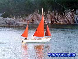 Boats of the «Drascombe» flotilla, which were described on this page, many lovers of water travel are interested. Readers were attracted by the slender hull shapes designed by John Watkinson based on the famous Newfoundland dories, the high seaworthiness of the boats (the article talked about sailing on «Drascombe Lugger» from England to Australia and across the Atlantic Ocean), the possibility of using them for mixed navigation — both on rivers and with access to the sea, the presence of both the motor, sails and oars, and many other advantages of the «Drascombe», which were described in the mentioned article.
The drawings of the motor-sailing dory offered to the attention of amateur shipbuilders are developed according to the materials provided by the editorial office of the collection of materials from the company «Honnor Marin» — builder serial vessels of the «Drascombe Lugger» type. When preparing the project, the real possibilities of «home shipyards» were taken into account, the most affordable materials in our conditions were used.
| Basic data of the boat «Drascombe» | |
|---|---|
| Longest length, m | 5,7 |
| KVL length, m | 4,6 |
| Maximum width, m | 1,91 |
| Width by KVL, m | 1,52 |
| Draft by hull, m | 0,26 |
| Draft with shvert, m | 1,2 |
| Weight of the boat with full rigging, kg | 380 |
| Displacement at draft by KVL, kg | 550 |
| Sail area, sq. m. | 12,3 |
| Recommended outboard motor power, hp | 3-8 |
| Speed with PM «Surf» (5 hp), km/h | 11 |
The project of the motor-sailing dory «Drascombe»
| Table of plasma ordinates | ||||||||||||
|---|---|---|---|---|---|---|---|---|---|---|---|---|
| Line | frame no. | |||||||||||
| 0 | 1 | 2 | 3 | 4 | 5 | 6 | 7 | 8 | 9 | 10 | Tr. | |
| Heights from OL. mm | ||||||||||||
| Keel — LC | 260 | 61 | 10 | 0 | 7 | 25 | 51 | 88 | 128 | 173 | 221 | — |
| Groove — P1 | 355 | 300 | 250 | 215 | 186 | 176 | 179 | 190 | 210 | 235 | 263 | 265 |
| Groove — P2 | 520 | 456 | 405 | 360 | 325 | 310 | 310 | 324 | 348 | 378 | 405 | 415 |
| Groove — P3 | 740 | 680 | 624 | 580 | 550 | 530 | 522 | 534 | 560 | 593 | 628 | 667 |
| Board — LB | 965 | 910 | 864 | 825 | 792 | 778 | 762 | 760 | 760 | 770 | 780 | — |
| Half-width from DP, mm | ||||||||||||
| Board — LB | 286 | 510 | 689 | 820 | 900 | 945 | 955 | 932 | 880 | 795 | 685 | 545 |
| Groove — P3 | 230 | 466 | 655 | 800 | 895 | 945 | 955 | 932 | 880 | 795 | 685 | 545 |
| Groove — P2 | 140 | 363 | 551 | 699 | 795 | 848 | 860 | 838 | 784 | 705 | 608 | 555 |
| Groove — P1 | 52 | 225 | 380 | 510 | 605 | 660 | 671 | 649 | 595 | 514 | 415 | — |
Theoretical drawing of a motor-sailing dory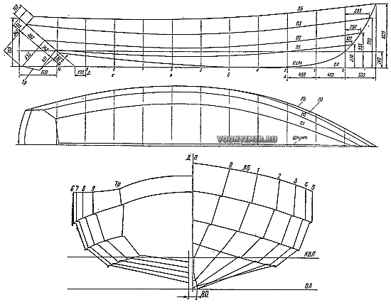 Zoom in 1824x1424, 179 kb |
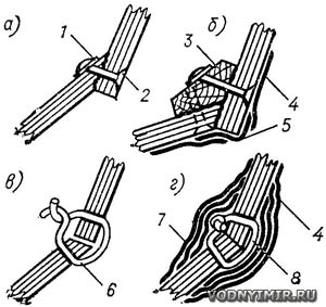 Methods of casing: a — inside («clinker»); b — using a bar (at the aft end); c — butt-to-butt using wire clips; d — groove in the final form. 1 — a copper washer; 2 — a rivet nail; 3 — a bar; 4 — the main fiberglass pasting; 5 — a fiberglass ribbon along the edge of the belt; 6 — a copper wire clip with a diameter of 2-2.5 mm; 7,8 — fiberglass strips along the joint. |
The hull is sheathed with strips of bakelized plywood with a thickness of 7 mm using the «edge to edge» (clinker) method; plywood is also widely used in the construction of bulkhead frames, side seats and decks. When installing the cladding on each groove, the plywood belts are glued and riveted with 3 mm copper nails-rivets on washers in increments of 60-80 mm. The resulting thickenings in the places of the re-cutting of the belts (it should be within 15-20 mm) serve as a kind of longitudinal stiffening ribs, which makes it possible to obtain a sufficiently strong body with a small number of set nodes; there are only five frames. In addition, vertical walls and horizontal surfaces of longitudinal cans and decks play an important role in ensuring the rigidity and strength of the hull.
You can also offer another, more modern method of building a building with the same «faceted» contours. The belts are sewn together with copper wire clips, and then the grooves are glued on both sides in several layers with fiberglass tapes on epoxy resin. Paper clips are mainly an assembly means of connection, the main role in ensuring the strength is played by fiberglass. (This method is briefly described in the article about the ace «Jack Shprot», see here); Leningrad amateur shipbuilders used it to build an 8-meter plywood yacht, and instead of paper clips they used a strong nylon thread!)
In terms of labor intensity and reliability, both methods are approximately equivalent. However, many proponents of clinker cladding believe that the protruding edges of the upper belts reflect splashes well and help to moderate pitching in the excitement. It should be borne in mind when using the second method that with insufficiently good gluing of the grooves with fiberglass, moisture may get into them and rapid rotting of wood, which turns out to be closed on both sides with fiberglass.
As a guide to the construction of the hull, its pasting with fiberglass and painting, as well as sewing sails, we can recommend the book «15 projects of ships for amateur construction», published by Shipbuilding in 1974 and 1975. Let us dwell here only on some of the features of the manufacture of the hull of the Dory boat and its armament.
Patterns and a bookmark on the slipway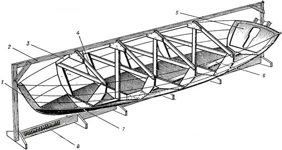 1 — stem; 2 — upper slipway; 3 — spacers of the pattern; 4 — pattern; 5 — transom; 6 — keel; 7 — bottom belt of the outer skin; 8 — lower slipway. |
It is more convenient to assemble the hull on the slipway in the normal position, i.e. down the keel. The edges of the skin are placed on transverse patterns mounted on a pre-assembled bookmark — a keel with a stem and transom. When making patterns (they correspond to the 2, 4, 6 and 8 frames of the theoretical drawing), the thickness of the skin must be postponed inside the outline of the frames, since the ordinate table is drawn up on the outer surface of the skin. The positions of the edges of the upper belts are taken as the lines of the grooves in it.
Housing design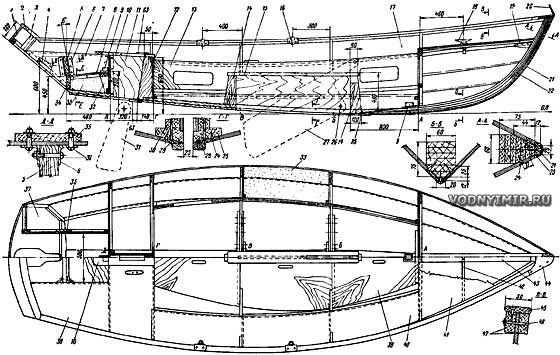 Zoom in, 2487x2040, 656 kb 1 — sideboard, plywood 2 layers δ=6; 2 — sideboard gunwale, 20x50, oak; 3 — corner beam, billet 40x80; 4 — rail 28X28; 5 — engine board, 38x150x150; 6 — square 3x32x32, L=150; 7 — longitudinal bulkhead recess, plywood, δ=7; 8 — recess pallet, plywood δ=7; 9 — mast steps; 10 — steering well gunwale, 20x170x600, oak; 11 — steering well wall, plywood δ=7; 12 — key wells, δ=34, oak; 13 — longitudinal bank bulkhead, plywood δ=5-6; 14 — shvert well key, δ=25, oak; 15 — gunwale of the mooring well, 22x110, oak; 16 — poduklyuchina; 17 — lining of the side and bottom, backfanner δ=7; 18 — mooring weft, L=220; 19 — brechtuk; 20 — stem-putens 4x22, steel; 21 — forging of the stem, segment 4x16, steel (to fasten on screws 3.5x25 with a step of 100 mm); 22 — stem, glue together from 8 rails with a cross section of 10x60; 23 — oak lining 12x35; 24 — screw 4x30; staggered through 40 mm; 25 — keel, 30x150; 26 — shaft axis, diameter 14; 27 — shaft, δ=12-14, steel; 28 — falshkil, 20x80, oak; 29 — screw M6; 30 — well base, 28x100; 31 — rudder feather, δ=4-6, steel; 32 — 20x100 rack; 33 — foam; 34 — 30x220x500 board; 35 — 20x120 cushion; 36 — M5 screw; 37 — transom, plywood=7; 38 — poop deck, plywood=6; 39 — payoles, plywood δ#948;=6; 40 — flooring of longitudinal cans, plywood δ=6; 41 — tank deck, plywood δ=6; 42 — beams, 25x60; 43 — midway, 22x100; 44 — gunwale lining, plywood δ=12; 45 — gunwale, 12x50, oak; 46 — rivet diameter 3, copper; 47 — rail of the privalny beam, 20x40; 48 — beams of the transom 25x40 (glued together from three slats); 49 — transom binding 25x60; 50 - zygomatic stringer, 40x25, L = 500; 51 - toptimbers, δ = 22; 52 — flortimbers 22x40; 53 — bulkhead canvas, plywood δ=6; 54 — flor 22x80x300; 55 — sublegars 22x40; 55 — rail 25x25; 57 — well head, 22x160, oak; 58 — flortimbers 22x75; 59 — rail 22x30; 60 — beams, 22X70; 61 — baller, pipe 30x3, steel; 62 — cheeks of the baller, 3x130x170; 63 — lining — baller bearing, brass. 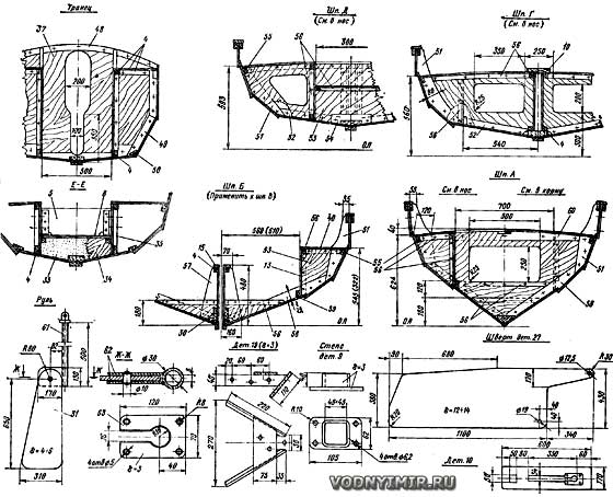 Zoom in, 2567x2056, 532 kb |
The keel and stem before installation on the slipway must be pre-riveted for a tight fit of the ends of the edges of the skin. The malka from the patterns is removed in place using a rail or a long sheet of sheathing plywood. To fit the edges of the skin, it is recommended to make a template from a strip of ordinary construction plywood or hardboard for the entire length of the body. Having fixed the template to the patterns with carnations, risks are applied to its inner side against the marks of the groove lines on each pattern. After removing the template, the edges of the future belt are drawn using a flexible rail for these risks. (At the same time, an allowance of 15-20 mm is given along the upper edge of all the belts, except for the shirstrek, specifically for the formation of a re-cut). Having imposed a template on a pre-glued belt blank, transfer it to it, pinning points with an awl, the outlines of the edges of the future belt and cut it out on them.
They begin the sheathing from the lower bottom belt, fixing it to the keel with 3x30 screws in 60 mm increments. In the aft part, the next belt approaches its edge already at some angle. This does not allow you to get the necessary overlap for riveting, so here it is better to connect the edges butt-to-butt on a backing bar or using paper clips and fiberglass sizing, as described above, by cutting the allowance along the upper edge of the bottom belt at the appropriate length. The adjacent surfaces of the edges of the belts are carefully cleaned and smeared with glue before riveting.
At the stem of the belt skin should be joined together. Here, at a distance of about 809 mm, you will have to remove the chamfer — touch, cutting off the angle, both the upper edge of the previously placed belt and the inner surface of the lower edge of the next belt. (Professional builders make samples in both edges according to the type of sheet pile, but this requires very careful execution.)
Sailing armament of the boat «Drascombe»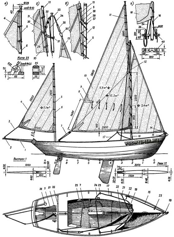 Zoom in, 1976x2503, 776 kb a — top of the mizzen mast; b — top of the mainmast; c — fastening of the rail and sail to the mainmast; d — fastening of the main halyard and tack; 1 — mizzen shot; 2 — mizzen sheet block; 3 — mizzen sheet; 4 — mizzen 2.1 m; 5 — seznevka, kapron 4-6 mm; 6 — mizzen mast; 7 — mainsail sheet; 8 — reef-krengels; 9 — reef-stern; 10 — mainsail 6,8 m; 11 — rail; 12 — mainmast; 13 — staysail 3,4 m; 14 — drum of the device for twisting the staysail; 15 — cable twisting the staysail; 16 — tack; 17 — staysail-sheet; 18 — shtag-putens; 19 — shroud, steel cable 2.5-3.2 mm; 20 — weft for the twist rope; 21 — shroud-putens; 22 — shvert-hoists; 23 — stack of staysail-sheet, textolite; 24 — sheet stopper; 25 — mainsail-sheet weft; 26 — mainsail shoulder straps-sheet; 27 — mizzen sheet duck; 28 — shot steps, oak; 29 — bayfoot, nylon Ø 6 mm; 30 — rail sling, nylon Ø 6 mm; 31 — chicks, oak; 32 — mainsail block; 33 — sling; 34 — mainsail; 35 — plank for adjusting the tension of the rod and shrouds (6 pieces); 35 — swivel; 37 — balls-rakskloty, textolite; 38 — shackle rail; 39 — nagel, brass; 40 — coffel-nagel plank, oak; 41 — bracket with mainsail-sheet block; 42 — boss; 43 — finger Ø 8 mm; 44 — shroud-putens δ=3; 45 — plank 15x80x60, oak; 46 — screw M6; 47 — pad 20x50x100. |
 d — mainsail-sheet shoulder strap; e — shroud-putens. |
The belts are attached to the patterns temporarily (with nails) in such a way that when the entire skin is riveted, the patterns can be removed, replacing them with frames sequentially, and the holes from the nails used to wrap the screws into the frames. To simplify the installation of frames, it is recommended to adjust their parts adjacent to the skin separately and assemble the frames directly in the housing. At the time of these works, the sides at the place of installation of the frame need to be slightly diluted — by spreading the bars to the desired width. In the frames, it is necessary to make tie-ins in advance for the support rails of the longitudinal cans.
On the described dory, a «heavy» type screw is used, cut out of a 12-14 mm thick steel sheet. Its weight is about 45 kg, which, combined with dynamic loads when stranded or even just rolling, places increased demands on the strength of the mooring well. The base, spacer knits and dowels of the well must be made of oak, the walls are made of bakelized plywood with a thickness of 7-10 mm. It is best to tighten the base with bolts with a keel; only water-resistant glue should be used in all connections. The second well — smaller — is made for the lifting rudder.
Masts, shot and rails are solid, circular cross-section, however, it is better to glue every detail of two or four pine bars; glued mast turns out to be more durable and warps less with fluctuations in humidity.
The mizzen mast has no standing rigging; it is held in a metal step and a wooden partner — the gunwale of the steering well. The mainmast is supported by a pair of shrouds and a staff, the role of which can be performed by a steel cable along the front of the staysail, if a device for twisting it is installed, described in the aforementioned book «15 ship projects». Along the way, we note that when equipping a boat, another book by the same publishing house «Shipbuilding — Boats, boats and motors in questions and answers» (1977), in which there is a special chapter on the equipment of small sailing vessels, can be a useful guide. The mizzen shot needs to be made removable; this will simplify mooring with the stern to the boom and steering the boat when sails are not used. Despite the rather high water resistance of bakelized plywood, the open edges of the belts need good protection from moisture. The case should be pasted with fiberglass in two steps. First, you need to lay strips of fabric along all the outer edges (two or three layers), skipping the edge of the strip with a width of 25-40 mm on each belt. Then a strip of fiberglass is applied to the entire width of the belt with the overlap of previously pasted areas along its edges. Pasting the body with a whole panel at one time does not guarantee good quality: voids form in the corners along the edges of the belts, into which water subsequently penetrates.
For rowing, the boat needs to be equipped with a pair of removable transverse cans (with dimensions of 28x250x1200mm.), which would fit over the longitudinal seats and be fixed from displacement along the boat by simple limiters, for example, in the form of bosses attached to the sides at the front and rear edges of the cans. The optimal length of the oars for the dory is 3300 mm.
The unsinkability of the boat can be ensured by sealing the middle compartments under the longitudinal banks (between frames 4 and 6) or filling them with light foam. In the first case, it is necessary to provide hermetically sealed hatches in the vertical walls of the compartments for their periodic inspection, repair and drying.
Anticipating readers questions about the possibility of replacing waterproof plywood with other materials, we will answer that for the construction of a dori, fiberglass sheet, fiberglass and even ordinary construction plywood can be used if the cladding is pasted on top with several layers of fiberglass to obtain the necessary rigidity and strength. The thickness of the fiberglass lining is 4-5 mm, if it is additionally reinforced with a set of foam. If these materials are also unavailable, you can use slats or sheathe the body with wide belts glued along the edges of spruce or pine boards. The technology of building ships with such a skin is described in detail in the book «15 projects of ships».
Boat projects for self-construction
Share this page in the social. networks or bookmark:
