Structural components of wooden boat hulls
Despite the increasingly widespread use of relatively new materials, such as duralumin, weldable light alloys and fiberglass, wood is still most often used in the amateur construction of small vessels. Even today, wood remains the most affordable and easily processed material at home. An important advantage of wood is the relative freedom of choice of constructive solutions, i.e. modification of the structures of certain components of the housing, depending on the available capabilities. In such cases it is useful for amateur shipbuilders to know the proven standard versions of the same structural unit.
Some of these variants of the main components of the hull of a boat or motor boat (4-6 m long) and are considered in this article.
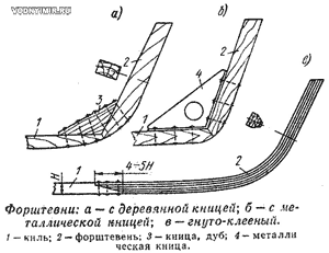 Stem. The best option from all points of view is a bent-glued (or laminated) stem, glued according to a template from thin pine or oak slats. Oak is preferable, which holds a large number of screws better and allows you to securely fix the outer skin with a minimum cross-section of the stem. Such a stem is connected to the keel usually with the help of an adhesive joint «on the mustache», duplicated by bolts or rivets.
To simplify the design, the straight stem is most often performed as a whole — from an inclined beam connected to the keel using a wooden or metal whip.
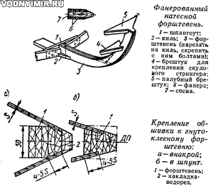 The curved stem of complex outlines is easiest to make composite (natural), having cut out separate parts of it from pine or oak boards; in order to preserve the strength weakened by the inevitable overgrowth of fibers, the entire stem on both sides must be pasted with thick plywood. If there is no board of suitable thickness, make the part flat-glued, i.e. cut it out of a pre-prepared «package» made of thin boards. When assembling the «package», try to make joints between the individual parts of each layer in different places — «disperse» the joints of adjacent layers.
The side faces of the stem must be appropriately prepared for fixing the ends of the boards (or plywood sheets) of the side skin converging in the nose. The simplest option is to remove the malki (this is done locally, i.e. when installing the skin on the assembled set), and after fixing the sides, protect the nose ends of the skin by installing another part — a water cut.
The width of the stem plane for fixing the plywood skin should be equal to 4-5 of its thickness, for the board skin — two thicknesses. For orientation, we note that the cross-section of the glued stem of a boat with a length of 5-6 m can be assumed to be 50x50 — 60 mm, motor boats with a length of less than 4.5 m — about 40x40 by 50 mm.
Keel. In most cases, the keel is located inside the hull, and the outer skin is protected by an overhead false keel. A variant of a composite keel of two parts is also possible — the outer (keel itself) and the inner (resenkil); the width of the resenkil for the possibility of attaching the outer skin should be greater than the keel.
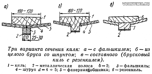
If there are difficulties with the selection of a high-quality bar or board of the right size, the keel is glued out of several layers of boards arranged horizontally and glued together along the formation (the joints are necessarily spaced along the length).
Keel sections are usually in the range from 20x80 to 30x120 mm. When installing a stationary engine, the keel should be somewhat more powerful than in the hull of a motor boat, and it is better to make it not from pine, but from oak or ash. In the place of the passage of the deadwood pipe, a steel strip must be applied to the keel, and in the area of the installation of the propeller shaft bracket, a bar with a length of one or two spats equal to it in cross-section should be placed on the keel inside the hull.
Typical structural midship frame of a boat
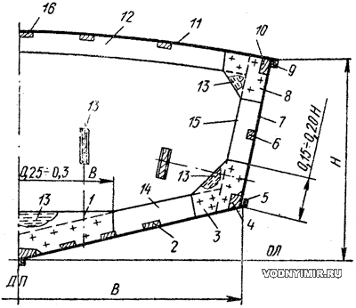
1 — flor, plywood on both sides; 2 — bottom stringer; 3 — zygomatic butt, plywood; 4 — zygomatic stringer; 5 — rebound bar; 6 — side stringer; 7 — side cladding, plywood; 8 — beam butt; 9 — collar; 10 — internal anchor beam; 11 — deck; 12 — beams; 13 — filler; 14 — bottom branch (flortimbers); 15 — side branch (toptimbers); 16 — carlengs.
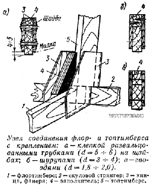 Cross set. The frames of sharp-cheeked boats, as a rule, are made up of composite — from the side parts (toptimbers) and bottom (flortimbers), which are connected on the flora and zygomatic knits. The thickness of the frames usually ranges from 15-18 mm. The knits and flora connecting the individual parts — the branches of the frame, are usually cut out of plywood and placed on both sides of the joint. On the frames that will be malkovat, it is recommended that the knits and flora from the outside of the frame should not be brought to the edge by 4-5 mm in order to avoid splitting the plywood when malkovat. The thickness of plywood knits and floors is taken to be equal to about 0.25 of the thickness of the frame, metal — about 0.10 of the thickness of the frame. The height of the knits is usually equal to 0.15-0.20 of the side height, and the length of the flora in the middle part of the hull is 0.25-0.30 of the width of the hull along the cheekbone. A filler is necessarily placed, which increases the strength and durability of the joint. Flora and knits are attached to glue with pressing nails. In the absence of glue, you can put it on thickly rubbed paint, but then nails cannot be used: you need to put bolts, rivets from rolled tubes or screws.
The details of the frame frame themselves — flortimbers, toptimbers and beams are usually made of pine. In some cases (with complex contours of the hull), it is better to cut the bottom branches of the frame from oak or ash. The height of the toptimbers on boats is assumed to be 50-60 mm, the flortimbers 70-100 mm; on motor boats 40-50 and 70-80 mm, respectively.
The spacer (the distance between the frames), as a rule, is in the range of 450-600 mm.
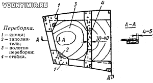 Bulkheads on small vessels are made of single-layer plywood, which is attached directly to a conventional frame. The thickness of the bulkhead web is approximately 0.25 of the thickness of the frame. Usually it is necessary to reinforce the canvas with two or three vertical racks or horizontal ribs — shelves. The racks must be connected to the beams and the bottom branches of the frame.
Longitudinal set. The longitudinal set of the sharp-cheeked body consists of zygomatic stringers, side stringers, bottom stringers, rest bars and carlengs. Their recommended cross-sections (pine) are indicated in the table.
Approximate cross sections of beams of a longitudinal set
| Name of the beam | Motorboat | Boat |
| Zygomatic stringer (blank) | 30x40 | 30x60, 50x50 |
| Side stringer, break beam | 20x40 | 20x60 |
| Bottom stringer | 20x30 | 30x35 |
| Karlengs | 20x20 | 20x30, 20x40 |
Most often, flortimbers are cut into bottom stringers, but sometimes a set system is also used, in which powerful frames pass over frequently placed stringers and are not attached directly to the skin.
The connection of the parts of the transverse and longitudinal set with each other is often carried out with the installation, in addition to the usual fasteners (and glue), metal squares-shorties. The zygomatic and side stringers, as well as the rest bars, are connected to the stem transom by horizontal knits — braces. Various variants of commonly used compounds are shown in the sketch.
Examples of constructive solutions of plywood housing units
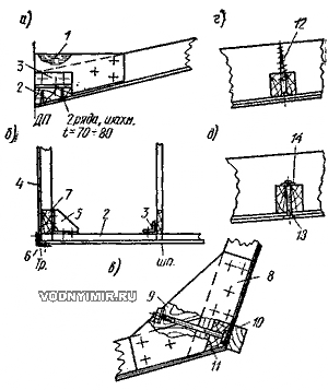
a — fastening of the keel to the frame and the skin to the keel; b — the keel to the transom and frames; c — the zygomatic stringer to the frame; d — the bottom stringer to the frame; d — the skin to the stringer.
1 — filler; 2 — keel; 3 — shorty (metal square 50x50x3); 4 — transom; 5 — steel starnknitsa; 6 — metal edging; 7 — transom binding; 8 — knits on both sides; 9 — filler; 10 — jack bar; 11 — bolt d=5-6; 12 — screw A4x60; 13 — red nail d=3; 14 — washer.
Transom. Like bulkheads, the transom consists of a frame-binding, usually assembled from bars 25-30 mm thick, and a panel sawn from plywood 4-5 mm thick on boats and 6-8 mm on motor boats. An outboard motor is mounted on the transom of the motor boat, so increased strength is required from the design. The longitudinal connections of the bottom and side set must be securely tied with the transom. On the keel, it is best to put a powerful welded mill (starnknitsa), preferably of light alloys. The bottom stringers and transom struts can be connected with plywood sheaths 8-10 mm thick. The side and zygomatic stringers are connected to the transom strapping with the help of 50x50x3-sized short corners, and the rest bars are horizontal knits (braces). At the level of the motor clamps, the transom of a motor boat is usually reinforced with a powerful beam — board from side to side. On boats with relatively powerful motors at the transom, niches (recesses) are often equipped, which are also important elements of the rigidity of the transom.
Transom of the boat
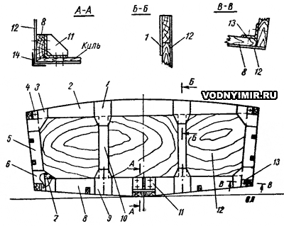
1, 9 — knits; 2 — beams of the binding; 3 — knits; 4 — a square (shorty); 5 — side branch of the binding (toptimbers); 6 — knits; 7 — filler; 8 — bottom branch of the binding (flortimbers); 10 — rack; 11 — transom door (starnknitsa); 12 — sheathing; plywood δ=5; 13 — square (shorty); 14 — shackle.
Transom of the motor boat: a — with a high side; b — with a low side
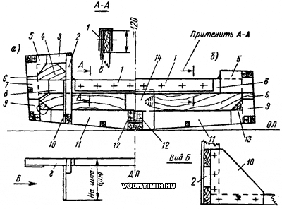
1 — shackle; 2 — stand; 3 — half-beam strapping; 4 — sheathing; 5 — knits; 6 — side branch strapping; 7 — knits; 8 — engine board; 9 — zygomatic knits; 10 — knits; 11 — bottom branch strapping: 12 — metal starnknitsa: 13 — filler; 14 — rack in DP (with plywood stitching). The joints of the ends of the zygomatic stringers and the rest bars with strapping are on steel shorties.
The transom of a boat with a stationary engine must be reinforced with racks installed in the plane of the foundation beams.
In all cases, after the assembly of the body is completed, an angular forging made of thin steel or brass with a size of 30x30x1.5 (2.0) mm should be installed along the perimeter of the transom.
Foundation. The foundation for the stationary motor of the boat is designed taking into account the dimensions, weight and power of the installed engine, as well as the nature, magnitude and direction of the forces that fall on the structure. Usually the foundation is a system of longitudinal and transverse beams securely attached to a set of housing. The foundation beams themselves, as a rule, are made of water-resistant plywood 8-10 mm thick, a metal square along the upper edge and pine (or oak) bruskov.
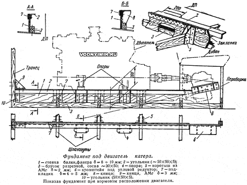
The beam shown in the sketch can be used to install engines weighing about 350 kg and with a capacity of up to 100-120 hp. The engine is attached to a 50x50x5 metal square connected to the beam with rivets or screws on a metal lining strip 4-5 mm thick. It is recommended to weld separate support pads under the paws of the engine to the square. Along the lower edge of the beam, bars with a length of a spatula are adjusted in place, which are fixed to the plywood wall with bolts; the bottom lining is attached to these bars with screws from the outside of the body.
Brackets for mounting the angular reverse gear are also attached to the foundation beams. In order to facilitate the design, it is recommended that all metal parts be made of a light alloy.
The outer skin. The skin of sharp-cheeked motor boats is most often made of water-resistant plywood 4-5 mm thick (on boats 7-8 mm on the bottom and 5 mm on the sides). The most widespread is waterproof plywood of BS-1 or FSF grades (applied thicknesses: 3, 4, 5, 6, 8 and 10 mm) and bakelized plywood (5 and 7 mm thick). Dimensions of plywood sheets: BS-1 and FSF grades 1525x1525 mm, bakelized 1200x4850, 1200x5600.
Double diagonal skin schemes

a — with mutually perpendicular layers; b — diagonal-longitudinal; c — cross section of the housing. A burlap pad on the paint is shaded.
The plywood covering is placed on a thickly rubbed paint and attached to the set with screws, nails and screws. Note that it is not recommended to put screws on bottom stringers on high-speed boats, it is better to use rivets.
Waterproofness at the junctions of the sheets along the cheekbone, on the break beam and on the keel, as well as on the bulkheads, is provided by gaskets made of painted strips of burlap or mitcal.
The bottom of the boat can also be sheathed with a pine rail. Such a covering can be made flat, on grooved rails and multilayer diagonal. It is recommended to dial the lining from the slats with a cross section of 15x25 mm. The installation of the rails is carried out from the DP to the cheekbone of the hull symmetrically — on both sides at once; each of them is attached with screws to the set and nails to the previously installed rails. Between the slats on the inside, it is necessary to provide grooves so that when swelling there is no warping of the skin.
Skin made of rails
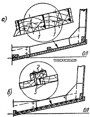
a — painted flat; b — on grooved rails (without embedding them in the frame).
1 — nail (nagel) into the edge: 2 — grooved rail; 3 — copper rivet.
The lining on the grooved rails is made of wide slats with a cross section of 12x50 mm. The thickness of the groove rails themselves from pine is usually assumed to be equal to the thickness of the skin, from oak — 0.8 of the thickness of the skin.
To simplify the work, the grooved rails are often not embedded in the frames, but installed when assembling the housing on top of a transverse set; in both cases, they are attached to the set with screws. The skin rails are attached to the grooved rails with red-colored nails-rivets with a step of 60-70 mm. The installation of rails is carried out from the DP to the cheekbones.
After covering the body with a rail, it is recommended to touch and clean the front surface, and then glue the bottom outside with 2-3 layers of fiberglass on polyester or epoxy resin. This will significantly increase the durability of the case.
Multilayer diagonal lining on boats is made of two layers of pine slats with a cross section of 8x30-50mm (depending on the complexity of the contours of the hull). The slats of the inner layer are located at an angle of 45-60° to the DP, are laid with a small gap (0.5-1.0 mm) and are attached to the frames with screws. Then a layer of thickly rubbed oil paint is applied to them and a burlap (or mitcal) soaked in the same paint is laid. After that, the second — outer layer of slats is placed, laid perpendicular to the direction of the slats of the first layer. Sometimes the slats of this layer are located along the keel. Both layers of rails are connected together by red-colored rivets with a step of 60-70 mm. Special attention should be paid to the sealing of the ends of the rails. Along the keel, the ends are protected with thickly rubbed paint and tongue-and-groove, and along the cheekbone with paint and a jackbar or brass strip.
Due to the bonding of layers over their entire area, the multilayer skin has high rigidity; with this design of the skin, longitudinal connections along the bottom can be minimized.
To ensure the durability of the hull, metal strips must be installed along the keel, stem and anchor bars.
We give examples of structural components of the connections of the side with the deck and the superstructure with the deck, as well as some normative data on various types of connections developed by the practice of construction and operation of small wooden vessels.
Typical structural connection nodes
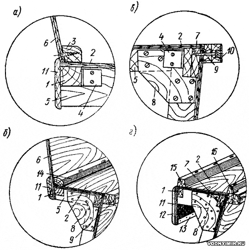
a, b — superstructures with hull; c — decks and sides; g — lining of the cockpit cutout on an open boat.
1 — karlengs; 2 — deck decking; 3 — strapping of the longitudinal coaming; 4 — 2x50x50 square; 5 — half-beams; 6 — longitudinal coaming of the cabin; 7 — internal timber glued from two rails during the assembly of the hull; 8 — beam knits; 9 — collar; 10 — metal protective lining-strip; 11 — lining (gunwale); 12 — soft stitching; 13 — strip for fastening the edge of the stitching; 14 — corner bead R=25; 15 — coaming 30x30; 16 — bulwark 20x30.
Bolted connections. The diameter of the bolt d, as a rule, is equal to 10-15% of its length. The distance between the axes of the bolts is usually maintained equal to at least 6 along the fibers and 3d across the fibers. The distance from the bolt axis to the edge of the part should be at least 2.5 d, and to the end — at least 6-8d (when attaching the ends of the sheathing boards to the set, this distance should be reduced to 3-5d).
Connections on rivets. The distance along the fibers between the axes of the rivets is set depending on the ratio of the smaller of the thicknesses S of the connected parts to the diameter of the rivet d. At S:d=10, this distance must be at least 10d, at S:d=4 — at least 20d. The distance from the rivet axis to the end of the part is usually assumed to be at least 10d, but in cases where this is caused by the features of the node, it can be reduced to 6d.
In plywood constructions, the distance between the rows of rivets with their chain arrangement should be at least 6-8d, and with staggered — at least 3-4d; the distance from the edge of the part should not be less than 4-6d.
The best material for rivets (in all cases) is red copper.
Connections on nails and screws. Round and square nails and especially screws are widely used as non-through fasteners. The length of the screws should be 2.5 thicknesses of the attached part, the pitch should be at least 10-12d. The diameter of the hole drilled for the screw in the structure should be no more than 0.8 d of the screw.
The material of nails is red copper or steel, screws are brass or steel. All steel fasteners must be cadmium-plated or galvanized.
Adhesive joints. The most commonly used glue is VIAM-BZ based on the resin VIAM-B, obtained from phenol and formaldehyde. The adhesive solution should be used within 3-4 hours after preparation. The thickness of the adhesive layer in the joint should be no more than 0.1-0.15 mm. Complete hardening of the glue (at a temperature not lower than 16° C) occurs within 1.5-2 days.
BF-2 glue can also be used for gluing wooden structures. When gluing, the parts of the set are maintained under pressure created by means of clamps, tightening with bolts or laying the load.
Extension of parts along the length. To connect the parts, as a rule, a butt joint (mustache) is used, the length of which is determined by the formula I=kS, where S is the thickness of the part to be glued, and k is a coefficient depending on the working conditions of the joint and the type of wood. For critical joints, when it is required to ensure equal strength with whole wood, when using pine and spruce of medium quality k=10-12, pine and oak of selected quality k — 12-15, in plywood joints k — 20. For most components of the housing, these values can be reduced by half, since the dimensions of the parts assigned based on technological considerations are obviously larger than required by calculation.
Butt joints
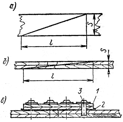
a — details of the set «on the mustache»; b — plywood lining «on the mustache»; c — plywood lining butt-on the lining.
1 — butt strip; 2 — gasket of dyed burlap; 3 — rivet.
Radii when bending. When performing bent-glued structures (stem, beams, etc.), it should be borne in mind that the bending radius should not be less than the values indicated in the table.
| The thickness of the board (rail), mm | Bending radius, mm | |
| pine | oak | |
| 5 | 400 | 400 |
| 7 | 500 | 450 |
| 10 | 1000 | 800 |
| 15 | 1400 | 1200 |
| 20 | 2200 | 1750 |
| 25 | 2500 | 2000 |
Plywood sheeting sheets can also be joined on the lining for simplification. In this case, the edges are adjusted butt-to-butt, and a strip of plywood of the same thickness as the main sheets is applied from the inside of the case, with a burlap lining on thickly rubbed paint. The connection is riveted with red-colored rivets with washers.
In the section «Motorboats, boats, yachts — miscellaneous, reviews, tips»
Share this page in the social. networks or bookmark:
