Skif boat for cottages and fishing
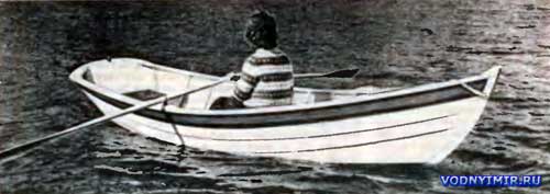
| Basic data of the skiff boat | |
|---|---|
| Longest length, m | 3,66 |
| Maximum width, m | 1,32 |
| The width is the largest on the bottom, m | 0,86 |
| Side height amidships, m | 0,39 |
| Body weight, kg | 65 |
| Passenger capacity, pers. | 3 |
Perhaps the construction of this simple boat will bring the least problems to people who have recently completed the construction of a country house or other building on a private plot. From the previous construction, there are almost always a few good boards, a lot of short-sized lumber. There is also a place for assembly, whether it is a shed or a shed. And since the manufacture of the hull does not require much time, it can be done even in the open air, closing the boat in bad weather with a piece of tarpaulin or polyethylene.
The hull of the boat has simple flat-bottomed contours. Very often, people who do not have sufficient experience in operating various types of boats treat punts with distrust: they, de, capsize, are flooded by a wave over the side, in a word, they are slaughterhouses.
Well, often such a reputation corresponds to reality. Especially if an ignorant person undertakes to build a punt, who is guided by his subjective ideas about the qualities of the vessel, depending on its size and shape. As a result, the shores of our rivers and lakes are filled with these very murderers, which are scary to push away from the pier, and not to go to a wide spill in windy weather.
Among the characteristic mistakes made by the builders of punts, it can be noted: insufficient width of the hull and the height of the side; vertical, without expansion to the top (collapse) of the side; lack of bending of the keel and saddle of the side; excessively lightweight hull design, which does not provide waterproofness of the skin, especially with variable exposure to water and the sun.
At the same time, there are quite a few seaworthy and safe-to-operate flat-bottomed boats. Let us recall, for example, the famous Newfoundland dories, on which, during the days of the sailing and steam fishing fleet, intensive fishing of cod and halibut was conducted in the North Atlantic, hundreds of miles from the coast. Or fishing boats of the skif type, which have become widespread in the shallow but vast bays of the North American continent. It is such a boat that it is recommended to build for readers of «Boats and Yachts», vacationing on the shores of lakes and large rivers.
Several years ago, the American boat magazine Woodenboat offered a team of three designers to reproduce the drawings of the most successful local-built Scythians and organized their construction at a small shipyard. Positive feedback from fans who purchased such boats or built them themselves, and prompted the editorial board of «Boats and Yachts» to this publication.
Moreover, not so much material and fasteners are required to build a skiff boat, which in our time of universal scarcity is not of the last importance. Only for the lining of the sides it will be necessary to select 8 boards of 4-meter length, and short-sized boards with a length of no more than 850 mm will go to the bottom, which are easy to cut out of low-grade lumber.
The recommended oak and ash for some parts (stem, frames, zygomatic stringers) can be replaced with spruce and pine, although not without prejudice to the durability of the boat. The same can be said about fasteners: of course, the use of brass screws and copper nails will provide high-quality connections and prolong the service life of the vessel, but if necessary, you can do with steel (preferably galvanized).
Note that drawings of a skif-type boat have already been published in the «Boats and Yachts» (No. 42, 1973) and the book «15 projects of vessels for amateur construction» (L-d, «Shipbuilding», 1974, 1976 and 1980 editions). However, the boat offered to the readers, while retaining the characteristic features of the skiff, has a number of significant differences that improve its operational qualities.
First of all, this boat is smaller and lighter than the previous one. Its keel line has a greater bend, which not only facilitates rowing, but also allows, when approaching a shallow shore, to further «lay out» the nose on land and facilitates the exit of people from the boat. The narrower contours of the bottom at the transom contribute to an easy stroke on the oars: on the mentioned skiff, the stern is made wider specifically for the possibility of installing an outboard motor with a capacity of up to 8 hp. According to the published drawings, the boat is not designed for swimming under the engine, although nothing prevents making an appropriate cutout in the transom and installing a 2-strong «Salute».
The main difference is lighter and more reliable case design. The bottom is provided to be sheathed across with two layers of boards 9-10 mm thick with a layer of cotton fabric (calico, muslin, mitcal) laid between them on a liquid oil putty. Such a covering is good because in the period between uses, the skif can be stored on the shore without fear that the bottom will crack and flow.
As on the «real» Scythians of the past, the sides are provided to be sheathed in a straight line («edge to edge»). This allows you to use the same thin boards for the lining as for the bottom. In the redrawing of the edges, due to doubling the thickness, peculiar stiffeners are obtained; being riveted, this joint has excellent water resistance, which does not depend on fluctuations in the humidity of the sheathing boards.
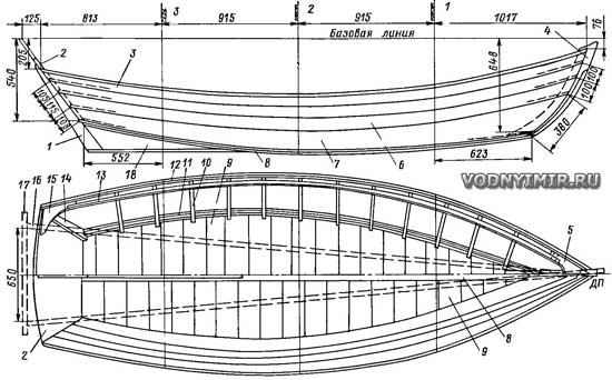
Assembly diagram of the skiff boat hull on the slipway
zoom in, 1692x1052, 252 KB
1 — rear stem, 22x80. oak; 2 — transom δ=20; 3 — shirstrek (upper belt) of the skin, δ=10; 4 — the outer part of the stem is a water cut δ=32, oak; 5 — breshtuk (made up of two parts), δ=28; 6 — the middle belts of the skin, δ=10; 7 — zygomatic belt, δ=10; 8 — keel 16x80, oak; 9 — bottom lining, inner layer, δ=10; 10 — frame, δ=16; 11 — zygomatic stringer 22x32, oak; 12 — collar 13x22; 13 — internal break beam 13x22; 14 — transom toptimbers 16x32, oak; 15 — starnknitsa δ=22; 16 — slipway beam; 17 — cross bar of the slipway; 18 — skeg (fin), δ=20, oak.
In addition to the outer keel, the bottom of the kit does not have, which is very convenient for fishermen, makes it easier to maintain cleanliness in the hull. Frames (more precisely, toptimbers) are provided only with the sides; here they connect the individual belts of the skin and hold the outer outline of the sides. The overall transverse strength of the body is given by three transverse seat banks, and the middle one can be made in the form of a fish box or a small locker, in which simple supplies can be placed — a ladle, falini (cables for mooring), etc. If a fish box is made, then a couple of holes can be drilled in the bottom so that the fish is constantly in fresh seawater. When the box is not in use, these holes are plugged with wooden stoppers.
Details about the manufacture of housing parts, its assembly and painting can be read in the aforementioned book «15 projects», here we will also indicate the general sequence of work and pay attention to the specific features of the construction technology and design.
The hull of the boat is formed on three transverse patterns, transom and stem, which are mounted on the slipway in the up position with the keel. In order for the boat to correspond to the drawings, the position of these parts is controlled relative to two mutually perpendicular planes — the horizontal base (it coincides with the upper edges of the slipway boards) and the vertical diametrical plane (DP) passing through the stem and the axis of symmetry of the transom.
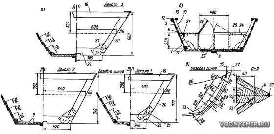
Patterns for the assembly of the hull (a); marking of the stem and the edges of the hull lining (c); midship frame (b)
zoom in, 1953x955, 180 KB
Pos. 1 — 18 — see the case assembly diagram;
19 — shergen-plank 20x120; 20 — toptimbers; 21 — zygomatic lining; 22 — floral pattern; 23 — inner part of the stem; δ=32, oak; 24 — bank (seat) 20x250; 25 — locker wall, δ=20; 26 — locker cover, 20x250; 27 — 16x32 can support bar.
On a sheet of plywood, cardboard or thick paper (for example, the reverse side of wallpaper), the outlines of the patterns, transom and stem are drawn in full size. The first two perpendicular lines should appear on this sheet — the base and DP, from which the dimensions of the patterns in half-width and height are postponed. It is necessary to draw a complete outline of each pattern — on both sides, since this drawing (a plasma breakdown) will also be used for assembling patterns.
Installing patterns on the slipway
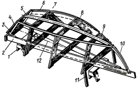
1 — trestle; 2 — slipway; 3 — temporary transom struts; 4 — transom; 5 — inner keel, cut into patterns; 6 — zygomatic stringer; 7, 8, 9 — patterns No. 3, No. 2 and No. 1; 10 — inner part stem; 11 — stand-stop pattern No. 1; 12 — string in DP.
From the scraps of any boards with a thickness of 16-20 mm, blanks for patterns are cut out, their edges are stretched, which will fit against the outer skin or the slipway bars. Having applied the blank patterns to the plaz marking in such a way that the planed edges coincide with the lines in the drawing, the pattern is assembled on nails and the risks are transferred to the flor and the shergen-plank position of the DP, and to the side branches — the lines of the board. It is convenient to apply control risks with a ballpoint pen.
For the transom, dry pine or spruce boards carefully prostrated to a thickness of 20 mm are used. These boards should not be wider than 100 mm, so that when the humidity changes, the transom does not warp, and the grooves do not crack. For the same purpose, it is recommended to connect individual boards to each other on wooden cylindrical spikes and water-resistant glue. From the side and bottom edges of the transom, it is necessary to remove the malka — to adjust the angle indicated in the drawing for a tight fit of the cladding boards. Since the screws screwed into the end of the board do not hold the load, to attach the outer skin to the transom from its inner side, 14 slats with a cross section of 16x32 mm (preferably oak or ash) should be attached. A DP line is also applied to the plane of the transom.
The stem consists of two parts — internal and external (water cut). They are cut according to the markings from an oak or ash board with a thickness of 32 mm. Soft woods are unsuitable here, since a lot of screws are screwed into the stem, fastening the edges of the outer skin and weakening its strength.
The assembly slipway can be assembled from one or two sufficiently rigid boards; it is important that the patterns on it are securely fixed and cannot change positions under the action of forces arising during the assembly of the skin. In the construction proposed in the figures, the main slipway bars should be made of boards with a cross section of at least 40x120. For the convenience of work, the frame of the slipway is placed on trestles about 0.5 m high or attached to pillars dug into the ground. The horizontality of the upper edges (the base plane) is verified using the level; the position of the DP is indicated by a tightly stretched steel wire.
Boat on the slipway
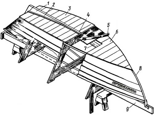
1 — fin (skeg); 2 — side part of the keel; 3 — outer layer of the bottom lining; 4 — keel; 5 — fabric gasket on putty; 6 — inner layer of the bottom lining; 7 — temporary keel; 8 — stem; 9 — slipway.
Before installation on the slipway, cutouts are made in the patterns for the zygomatic stringers and the temporary inner keel rail, which is removed after the body is manufactured. Transverse patterns are placed on the slipway strictly vertically, and to attach the transom at the right angle, you will need to put a pair of inclined slats with racks, sewing them to the slipway. The risks of DP on the shergen planks of the patterns should coincide with the string stretched on the slipway, and the verticality of the planes of the patterns should be checked by the plumb line, making sure at the same time that the plumb line lowered from the risks of DP on the flora falls on the DP string on the slipway. Finally, the patterns, transom and stem are loosened with temporary spacers, excluding their displacement during further work.
Since the belts of the side skin are not attached to the patterns, you can not remove the malka from the patterns. But for this, the patterns need to be set as shown in the figure: in patterns No. 1 and 2, combine their bow edge with the theoretical line on the slipway, in patterns No. 3 — the stern.
Now it is possible to link all these details together using a temporary internal keel. The end of this rail is attached to the transom with the help of a short bar. At the bow end, a nest is made for impaling on the stem. Since the internal keel is not needed in the finished hull, it must be removed along with the patterns when removing the hull from the slipway.
If it is possible to get a pair of suitable oak or ash slats for zygomatic stringers, it is best to steam them before installing them in place. When steamed, the rigid oak rail becomes very malleable and bends around the patterns without much effort. For steaming, the rails are placed in a steel pipe of a suitable diameter and length, a wooden stopper is hammered on one side and, after pouring a little water, heated over a fire. As the water evaporates, it is topped up from the kettle. Approximately 30 minutes after the water boils, the rail is ready to be installed in place. Stringer patterns are attached temporarily with nails, to the transom and stem permanently with 3x25 mm screws.
The upturned edges of the stringers tremble (remove the malka) until the boards of the bottom lining fit snugly. The control is carried out by applying a bar with a straight edge to the stringers. The temporary keel inside the boat should serve only as an intermediate support for the thin planks of the skin until its second layer is installed.
The bottom is sheathed with transverse strips of spruce or pine boards with a thickness of 10 mm and a width of no more than 150 mm. The first layer of boards is attached to the zygomatic stringers with nails 2x25 mm and then cut flush with the surface of the stringer. In the future, the ends of the slats of this layer are covered by the zygomatic belt of the side covering.
The body assembly; a — the sequence of the bottom lining
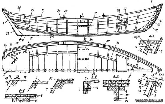
zoom in, 1611x1018, 258 KB
Pos. 1 — 27 cm on the housing assembly diagram and the drawing of the patterns;
28 — 20x250 jar; 9 — strip 2,5x19, brass or steel digitized; 30 — poduklyuchina, steel; 31 — pillow poduklyuchiny 22x45x250; 32 — the wall of the fish box: δ=19; 33 — a layer of fabric on the putty.
It is not necessary to caulk the grooves between the slats (with such a thickness, it is useless); their water resistance is ensured by laying between the layers of fabric on the putty. And so that there is no leakage along the cheekbone, a thin waxed cotton flagellum can be laid under the ends of the boards on the stringer, which is crimped when setting nails.
Upon completion of the lining of the bottom, the ends of the slats are carefully cut along the contour and shaken with a plane together with the side edge of the stringer for the installation of the zygomatic belt of the lining. Previously, the nails with which they were attached to the patterns are removed from the stringers.
The zygomatic belt of the side covering is made of a wide (about 200 mm) uncut board with a thickness of 10 mm. Using the dimensions indicated in the drawing, the width of the belt is postponed on the stem, transom and patterns, appropriate risks are applied and the board is applied to the set. Temporarily press the belt to the zygomatic stringer and the patterns with clamps, then outline the outer contour of the edge of the bottom lining on it and transfer the risks from the patterns and the stem to the inner layer of the board. After removing the board from the set, its edges are cut off, sanded on the workbench on both sides.
The width of the re-cutting of the lining edges is 20 mm; the thickness of the connected edges is 6-7 mm. At the stem and transom, the edge of the belt superimposed on top has to be embedded (sunk) into the edge of the already supplied one. For this purpose, in the edge of the zygomatic belt, it is necessary to choose wedge-shaped recesses at a length of 300 mm from the bow and stern ends. This can be done with the help of a special planer-shpuntubel. The belt is placed on the workbench in such a way that the processed edge protrudes 20 mm beyond the edge of the workbench, a bar is temporarily nailed to the board, limiting the lateral movement of the tongue-and-groove. On the workbench, you can also remove the malka from the rest of the edge of the zygomatic belt.
Then the zygomatic belt is put in place, securing it with 25 mm screws to the stringer and stem and 32 mm screws to the transom. To guarantee waterproofness, a cotton flagellum is placed on the stem at the end of the board; the gap between the aft end of the belt and the transom can be caulked later — here the connection of the board with the set has a width sufficient to securely hold the caulking. The edge of the belt protruding above the first layer of the bottom lining is pulled flush with it to lay the second layer of the bottom lining.
It is better to first prepare all the slats of this layer (their thickness, like the first one, should be equal to 9-10 mm), since it is necessary to spread the grooves of both layers relative to each other, and after covering the bottom with a cloth, it will be difficult to do this. The slats are cut into a clean size, marked (we recommend doing this from the middle to the bow and stern) and stacked. It is good to cover their inner side and edges with drying oil — when laying on a fabric covered with putty, the wood will practically no longer «take away» the binder (drying oil) from the adhesive layer, so that the integrity of the protective film will not be violated. The surface of the first layer of the bottom must also be pre-peeled.
After drying of the drying oil, a thin layer of liquid putty is applied to the bottom with a spatula (drying oil — 250 g, turpentine — 20 g, siccative — 40 g, chalk — 690 g), cover the bottom with a carefully smoothed cloth and roll it to the lining with a roller so that the putty appears through the fabric. The edges of the fabric are bent on the sides, temporarily fixed with small nails; excess fabric is cut off.
Before laying each regular strip of the second layer of sheathing, a thin layer of putty should be applied to the fabric. The slats are attached to the zygomatic stringer with 3x32 screws, to the transom and stem — 3x40 mm. In addition, it is necessary to rivet the slats of both layers with 20 mm nails, which are placed along the grooves at a distance of at least 25 mm from the edge. To avoid splitting the slats at the nail outlet, it is advisable to pre-drill holes with a diameter of 0.1-0.2 mm smaller than the diameter of the nail.
Next, you can continue installing the side trim belts. In total, 4 belts will have to be put on each side (in a classic skiff, as a rule, the side was sheathed with only three belts, but this was at a time when wide boards did not pose a problem for shipbuilders). In the redrawing from the edges of adjacent belts, it is necessary to remove the malka until they fit snugly to each other. The edges, carefully fitted and riveted with nails, do not need caulking and remain water resistant to any changes in the humidity of the boards.
Fitting of the belt lining of the side at the stem (transom) (a) and the recess in the upper edge of the belt (b)
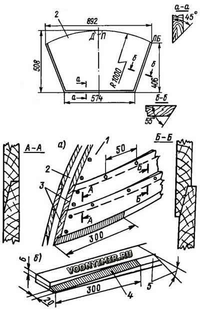
1 — the zygomatic belt; 2 — the stem; 3 — the intermediate belts; 4 — the recess for the edge of the superimposed belt; 5 — the angle of the bevel edge.
The work of fitting is facilitated by a small template with a malkovannoy edge, which is applied on each pattern to the edge of the already supplied belt, as shown in the figure. In these places (on patterns), using a chisel, a small piece of the desired size is removed from this edge, then it is shaken with a plane along the entire length in such a way that one smooth surface is obtained. From the mating edge of the new belt (it is the lower one, if we consider the body in the normal position — bottom down), the malka can be pre-removed on the workbench, since it corresponds to the malka of the template and is constant along the entire length of the belt.
In order to correctly carve out the belt of the skin, you can use a thinner, narrower and lighter marking board. Previously, on all patterns, transom and stem, it is necessary to mark the position of the upper edge of each belt. The marking board is applied to the patterns approximately in the middle of the marked belt and fixed to them with clamps. Arc marks are applied to this board with a permanent solution of the compass, while the second leg of the compass is placed on the line indicating the width of the belt on the pattern, or on the edge of the already placed belt, where the lower edge of the marked belt should be after installation. On the marking board, you should mark a control line that determines its position along the length of the body, for example, outline the leading edge of the pattern No. 2.
Fitting of the edges of the side trim:
a — marking of the small with the help of a template; b — marking the width of the belt on the marking board; c — marking the belt on the marking board
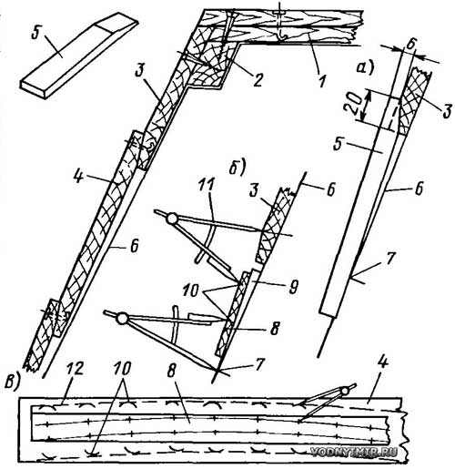
1 — bottom lining, 2 — zygomatic stringer; 3 — zygomatic belt; 4 — intermediate belts of the side; 5 — template for marking the small on the upper edge of the supplied belt; 6 — edge of the slipway pattern; 7 — risk indicating the position of the upper edge of the marked belt, 8 — marking board; 9 — wedges temporarily nailed to the pattern; 10 — serifs with compasses; 11 — marking compasses; 12 — contour of the belt edge.
After removing the marking board from the body, it is applied to the blank of the marked belt and the same solution of the compass is transferred to the corresponding sides of the blank. Then a flexible rail is applied to these serifs so that it touches each arc, and smooth lines of both edges are outlined. It remains to cut the board along the contour, touch the small along the lower edge, make wedge-shaped recesses at the transom and stem along the lower edge and you can put the belt in place.
First, it is pressed to the patterns with clamps and with the help of compasses, markings are made for nails that will be riveted to the mating edges. The distance between the nails is 50 mm; they need to be put with preliminary drilling of holes, bending the sharp end going inside the case. At the same time, it is necessary to hold the nail head outside with a heavy metal object in order to tightly compress the joint. If there are copper rivet nails and special (slightly conical) copper washers, then riveting can be used, although the «vzagib» fastening provides sufficient strength and groove density.
Similarly, the rest of the belts are put in place. The upper edge of the uppermost belt — the shirstrek — should not be malkovat. It is then slightly adjusted together with the internal privalny beam and collar.
Having pierced the joint of the skin with the transom, the hull can be freed from the slipway, turned over to the normal position and installed on trestles or keel blocks for the convenience of further work. Immediately it is necessary to stretch the sides with two temporary spacers so that the width of the boat does not decrease, and the hull itself would not receive a «twist».
Frame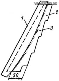 1 — a pattern made of cardboard or plywood; 2 — a blank frame; 3 — a finishing edge of the frame. |
The next stage is the preparation and installation of side frames, which are recommended to be made of oak or ash. The blanks are stretched to a thickness of 16 mm, but with an allowance for width and length. Having marked the position of the frames on the inner surface of the sides, each of them is adjusted to its place. First, the socket for the zygomatic stringer is drawn and cut out, then the position of the edges of the lining edges is marked on the workpiece, for which appropriate cutouts need to be made. Above the edge in the frame there must be a water flow, otherwise moisture and dirt will accumulate at the junctions of the edges of the skin with the frames, and then rot will appear.
Having adjusted the frame to fit snugly to the skin, the width of the privalny beam (16 mm) and the zygomatic stringer (50 mm) are marked on it, then using a pattern cut out of cardboard or plywood, the inner edge is outlined. After its processing, the frame can be put in place by screwing two screws into each belt through the skin. With a screw, you need to fix the frame to the zygomatic stringer.
Next, the ends of the lining at the stem are shaken, carefully adjusted to it and put a water cut on screws and thiokol sealant (you can use thick-rubbed whitewash or epoxy putty). Its lower edge must be released below the bottom in order to close the front end of the keel. At the stem they put a brechtook, which consists of two parts connected by a DP «house». The annual layers in each part of the brechtuk should be located parallel to the shirstrek. At the transom, also with a slope to the horizontal, starnknits are installed. In them and the brechtook, you need to make cutouts for fixing the internal break bars. Before setting the rest bars, it's a good idea to make sure that the gap between the side and the beam in each frame is the same, otherwise you will have to adjust the upper ends of the frames. It is best to rivet the collar, the skin and the anchor beam on each frame with one copper rivet. Then you can adjust the upper surface of the side so that it is smooth and smooth.
The outer keel is prepared for the full length of the boat. Where the aft fin is installed, it is necessary to make two cuts in the keel along the thickness of the fin. Here, the middle part of the keel follows to the transom on top of the fin, and the side parts tightly compress the fin at its base at the bottom, increasing the strength of the joint. All screws in the keel and fin are wrapped from the inside of the boat through the bottom lining. Guide holes are pre-drilled for the screws from the outside.
The aft edge of the fin is cut off at the angle of the transom and closed from the outside with a bar of the stem. In the nose, the keel is stretched along the sides to the width of the water cut. Support rails for transverse cans are cut into the frames and a locker is mounted under the middle — rowing jar. If it is decided not to do it, the jar must be loosened with wooden knits on the sides.
Paddles, paddles and rowlocks can be used ready-made; the length of the paddle should be about 2400 mm with the length of the inner part — from the rowlock to the end of the handle 580-620 mm. Drawings for self-production can be found, for example, in the article on the construction of the Grayling boat in the «Boats and Yachts» No. 144.
When finishing and painting the boat, you can use the recommendations of the books «15 projects of ships» or «Handbook of boats, motorboats and motors», 1982, L-d, ed. «Shipbuilding».
Boat projects for self-construction
Share this page in the social. networks or bookmark:
