Repair of metal hulls of boats by welding
During the operation of metal boats and yachts, cracks, holes, dents and other defects appear in their hulls, in which the use of the vessel becomes impossible. Small holes in the housing with an area of up to 500 mm can be sealed with a thermoplastic composition consisting of fiberglass and polyvinyl butyral (see the article «Repair of metal hulls of boats using thermoplastics»). However, cracks formed in angular joints and larger holes can only be repaired by welding.
To eliminate defects in housings from for shipbuilding steel (in open areas), manual arc welding with coated electrodes, as well as gas welding are most acceptable.
For manual arc welding, electrodes of the E-138/45N, OMA-2, AN-X7, etc. are used. It must be remembered that it is very difficult to use manual arc welding with a thickness of 3 mm or less of the hull cladding sheets, since there is a danger of through-burning and penetration. To avoid this, it is recommended to use the following techniques: choose electrodes of the minimum diameter; use the welding current of the minimum possible value; in order to facilitate the ignition of the arc and increase its stability, include an oscillator in the welding circuit; use copper gaskets, etc. P.
Manual arc welding is performed by direct and alternating current. When welding thin-sheet parts, it is advisable to use a direct current of reverse polarity, since in this case the arc gorenje is more stable and more heat is released at the positive pole than at the negative.
The technological process of welding is widely described in the technical literature, however, I would like to note a number of features. Steel 0.5-1.0 mm thick should be lap welded with penetration through the top sheet or butt-to-butt with laying between the welded edges of the steel strip. In the second case, the melting of the edges should occur with the indirect effect of the arc. In addition, steel can be welded with flanging edges. With a metal thickness of more than 1 mm, welding should be performed in accordance with GOST 5264-80. At the butt joint, welding is carried out on copper linings, since this method protects the metal from through-burning and promotes good formation
It is desirable to power the arc from the PS-100-1 converter or the TS-120 AC unit, since they are characterized by an increased no-load voltage and sufficiently small welding currents. Recommended welding modes are given in Table 1.
| Table 1. Recommended manual arc welding modes | |||||
|---|---|---|---|---|---|
| Metal thickness, mm | 0,5 | 1,0 | 1,5 | 2,0-2,5 | 3,0 |
| Diameter of the electrode, mm | 1 | 1,6-2,0 | 2 | 2,5-3 | 3 |
| Welding current, A | 10-20 | 25-35 | 40-50 | 60-90 | 80-130 |
The values of the welding tone, its type and polarity for an electrode of a particular brand are selected according to the electrode passport, which lists its welding and technological properties, the typical chemical composition of the seam and mechanical properties.
The minimum current strength is determined by the stability of the arc gorenje. Increased amperage causes overheating of the electrode, peeling of the coating from the rod, increased fumes and can lead to various defects.
Gas welding is also not free from a number of disadvantages, the main of which are the need for a strict dosage of acetylene-oxygen flame and a large heating zone, leading to increased deformations, therefore, a highly qualified specialist is required here (not lower than 5-6 discharge).
When performing gas welding, it is necessary that the welding flame has sufficient thermal power, depending on the thickness of the metal being welded and its properties. Sheets up to 4 mm thick must be welded in the left way to avoid burnout, i.e. by moving the filler rod and the burner flame to the left. With a thickness of up to 1 mm, the filler material is not used in the welding process.
For welding thin-sheet steels, a normal flame is required, which is provided at a ratio of oxygen to acetylene of 1:1.3. For such work, the injection burner «Baby» with a set of tips is convenient, the number of which is selected depending on the thickness of the parts being welded (Table 2).
| Table 2. Selection of «Baby» burner tips | ||
|---|---|---|
| Metal thickness, mm | Diameter of the filler wire, mm | burner tip no. |
| Up to 1.5 | 1,5 | 1 |
| 1,5-2,5 | 2 | 2 |
| 2,5-4,0 | 3 | 3 |
The main difficulty in welding aluminum alloys is the instant formation of an oxide film on their surface (AL2O3) with a melting point of 2050 °C and a density of 3.85 g/cm. The oxide film protects the metal from corrosion, but negatively affects the weldability, mechanical and other properties of the metal seam.
For the repair of aluminum alloy housings in open areas, it is most effective to clean the welded surfaces from oxide films by cathodic spraying, which is carried out during welding in a protective gas environment with reverse polarity. When the molten cathode is bombarded with heavy ions, the oxide film located on the surface of the bath and in the heated zone of the base metal splits and does not interfere with the normal formation of the seam.
This effect of removing oxide films is largely achieved when welding aluminum alloys with a stabilized arc. The technical possibilities of this method are investigated by the author of this article. In this work, the CA-367 burner was used, which is characterized by a high degree of arc stabilization, the possibility of its excitation by contact without adversely affecting the welding arc, as well as high arc stability when exposed to wind (up to 3 m/s) and drafts due to the double flow of protective gas coming out of the working honor of the burner.
The burner consists of a housing with a gas supply tube connected by an insulator to a copper tip cooled through a water pipe, into which a tungsten insert is pressed.
The water supply is connected to the water and current supply tube, and the tip through the sleeve is connected to the drain tube. The stabilizing (inner) nozzle 3 and the main (outer) nozzle 4 are located coaxially relative to the tip 2. Both nozzles are connected by holes for the passage of protective gas — argon of the highest or first grade according to GOST 10157-79.
During the operation of the burner, the protective gas through the tube 12 enters the cavity between the tip 2 and the housing 6. Part of the gas through the holes 5 enters the interstitial space, forming a protective gas flow. The main, swirling gas flow exits the annular gap between the tip 2 and the nozzle 3, forming a stabilizing flow.
When the arc is excited in contact, the discharge occurs at the end of the copper tip 2, after which the anode spot passes to the rapidly heated tungsten insert 1, which has a high thermal conductivity. In this case, the voltage has a minimum value and the arc becomes as stable as possible. For the convenience of contact excitation of the arc, the copper tip protrudes beyond the nozzle end by 1.5-2.0 mm (Fig. 1).
Fig. 1. Burner device
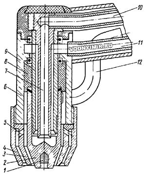
1 — tungsten insert; 2 — copper tip; 3 — stabilizing nozzle; 4 — main nozzle; 5 — holes for the passage of protective gas; 6 — burner housing; 7 — water supply; 8 — insulator; 9 — sleeve; 10 — water supply tube; 11 — drain pipe; 12 — gas supply pipe.
Note: The bimetallic electrode consists of a copper tip and a tungsten insert pressed into it.
When welding with a stabilized arc, high quality of the welded joint is ensured with an arc length of 5-8 mm; the consumption of protective gas is reduced by 2-3 times; there are no tungsten and gas inclusions in the welded joint.
The composition of the post for manual argon arc welding with a stabilized arc (Fig. 2) includes: a power source, current-carrying cables, a CA-367 burner, a hose for supplying protective gas, a water cooling system with a pump, a gas reducer with a pressure gauge, a cylinder with protective gas, a set of protective equipment (shield, gloves, apron, etc. d.), a set of tools and devices for quality control of the welded joint.
Fig. 2. The scheme of the stabilized arc welding post with contact arc excitation.
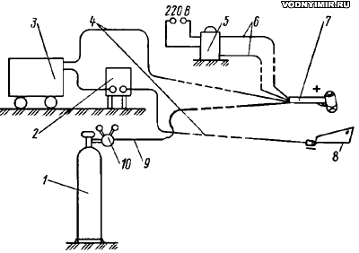
1 — cylinder with protective gas; 2 — ballast rheostat; 3 — power supply; 4 — current—carrying cables (minus per product); 5 — burner cooling system; 6 — hoses for supply and discharge of coolant; 7 — burner for welding with a stabilized arc; 8 — the product to be welded (boat or yacht); 9 — a hose for the supply of protective gas; 10 — a gas reducer with a pressure gauge.
As a power source, it is advisable to use rectifiers of the VDU-504, VD-301 brand and converters PSO-300, PS-300, PSO-500, PSU-500, etc. with falling external characteristics and an idle voltage of at least 60 V.
To cool the burner, it is advisable to use autonomous cooling systems, for example CA-429.15.00.00. The electromagnetic vibration pump of this system is powered by a 220 V mains voltage; distilled water circulating through the water paths (with a total volume of 10 liters) is practically not consumed. Water must be supplied to the burner at a pressure of at least 3 kgf/cm.
The author made a cooling system consisting of a welded tank with a capacity of about 12 liters, an electric pump of the PA-22 brand (used for cooling machined parts on lathes or milling machines — a capacity of 22 liters/min) and rubber hoses with an internal diameter of 5 mm. When working for an hour, the temperature of the water circulating in a closed circle in the cooling system did not rise above 40-45 °C.
The quality of welded joints of aluminum alloy structures is largely determined by the preparation of the surface of the edges to be welded and the filler wire.
Defective parts to be welded are cleaned of dirt and oil. To do this, they are washed with water, then with any solvent (acetone, white spirit, aviation gasoline, etc.) and wiped dry with a rag. The paint around the defective place is removed from the front and back sides at a distance of up to 200 mm from the place of suture application.
The torn edges of the hole must be leveled. The edit begins with the edge closest to the unevenness, on which a series of blows with a wooden hammer is applied within the convex area. All the burrs are cut off. At the ends of the cracks, a hole with a diameter of 3-5 mm is drilled to prevent their further spread.
The oxide film is removed to a matte sheen of metal at a width of at least 30 mm on both sides of the edges to be welded, as well as on the edges themselves (with a metal brush, scraper or file, immediately before welding). During operation, metal brushes should be periodically washed in a solvent.
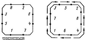
The holes are sealed by applying overlays in such a way that the overlay overlaps the edges of the hole by 10-15 mm. At the lining, it is desirable to cut the corners by 5% of the length of the larger side, clean its edges with a metal brush, degrease, and then pre-grab at least eight points. Tack and welding should be carried out in the order shown in Fig. 3.
Fig. 3. The scheme of the tack (left) and welding the lining to the hole
When sealing cracks after removing oil, paint and degreasing the surface, it is necessary to clean the defective places with a metal brush to a width of at least 30 mm on both sides of the crack. At a distance of 10-15 mm from the visible ends of the crack, holes with a diameter of 3-5 mm are drilled. The edges of the crack do not need to be cut. When welding cracks in metal up to 2 mm thick on the reverse side, it is desirable to have a lining to avoid burns.
The filler material for welding aluminum alloys is a welding wire with a diameter of 2-3 mm, similar or similar in chemical composition to the base metal (Table 3). After long-term storage and deconservation, it is recommended to subject it to chemical etching. If this is not possible, it is sufficient to remove the preservative grease from the wire before welding by wiping and degreasing with any solvent, clean it with medium or fine grit sandpaper, then wipe it thoroughly with a dry rag and degrease again.
| Table 3. Recommended grades of filler wire | |
|---|---|
| Welded metal | Brand of filler wire |
| AMg3 | St. AMg3, St. AMg5 |
| AMg5 | St. AMg5, St. AMg6, St. 1557, St. AMg61 |
| AMg6 | St. AMg6, St. AMg61, St. 1557 |
| AMg61 | St. AMg61, St. AMg5 |
| Note. The first of the specified names of the filler wire grades provide the highest quality characteristics of the welded joint. | |
The burner kit includes replaceable parts (bimetallic electrode, stabilizing and main nozzles), which are selected depending on the welding modes (Table 4). The numbering of replaceable parts is affixed to their side surface. For welding metal with a thickness of 1-5 mm, parts No. 1 are used. The pressure of argon in the gas line before entering the burner must be at least 2 at. After selecting and loosely fixing the replacement parts with a special socket wrench (it is available in the spare parts), the stabilizing nozzle is centered relative to the bimetallic electrode (the gap between them should be within 0.6-1.5 mm, depending on their number).
| Table 4. Recommended modes of stabilized arc welding | |||||
| Connection type | Metal thickness, mm | Arc current, A | Tense- nie, In |
Welding speed, m/h | Gas consumption, l/min |
| Butt with edge flanging | up to 1 | 40-60 | 22-24 | 15-30 | 3-4 |
| Butt joint without beveling edges in one pass on a removable gasket | 1-2 2-3 4 |
60-90 70-100 110-130 |
23-25 24-25 25-26 |
20-25 20-25 14-18 |
5-6 6 6-7 |
| Overlapping in one pass | 1-2 2-3 |
60-100 100-180 |
24-25 25-26 |
15-20 12-16 |
5-7 7-8 |
| Angular in one pass (T-shaped) | 2-3 | 90-110 | 25-26 | 20-30 | 5-6 |
Starting the weld, you need to warm up the edges to be joined and get a welding bath. This operation is carried out by slow reciprocating or circular movement of the arc on a small section of the seam. After the formation of the bath, the arc length is gradually increased: when welding butt joints without beveling edges up to 5-8 mm, when welding with beveled edges and in angular (T-shaped) joints — up to 8-12 mm.
If the repair is carried out under unfavorable conditions, when contact with a humid environment (water) is possible, it is advisable to warm the edges of the parts with argon before welding by moving the burner along the edges at high speed.
During welding, the burner axis should be positioned at an angle of 60-80° to the surface of the elements being welded (Fig. 4).
Fig. 4. The layout of the welding torch and the filler rod when welding with a stabilized arc
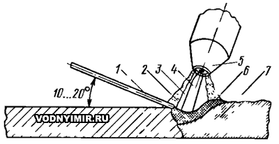
1 — filler rod; 2 — external, protective gas flow; 3 — internal stabilizing gas flow; 4 — welding arc column; 5 — CA-367 burner; 6 — molten metal; 7 — weld.
The angle between the burner axis and the filler wire can vary from 70 to 90°, but when welding in hard-to-reach places, it can vary over a wider range. Welding in the lower position can be performed without oscillation of the burner. In any case, the dimensions of the welding bath should be as small as possible. The welding process must be carried out at the maximum permissible speed, while it is necessary to strive to prevent the arc from breaking. It is necessary to introduce the filler wire into the welding bath at some distance from the arc column, while it should not leave the gas protection zone. After the end of welding and in case of a break, it is not recommended to abruptly tear off the welding arc; it is necessary to gradually increase the arc gap or reduce the amount of welding current.
When applying multilayer welds, each seam must be cleaned with a metal brush before applying the next one, and it is desirable to shift the beginning of a new seam relative to the other by 15-20 mm so that the craters do not lie on the same section.
The quality of welded joints is checked by external inspection. In the presence of defects (surface pores, inclusions, uncompleted craters, etc.), they are eliminated with subsequent welding of these areas. Before welding the areas where the metal with defects has been removed, their surface is degreased and cleaned. The welding mode is selected in the same way as when welding the corresponding joints.
Fig. 5. General view of the welding torch and replaceable parts 1-3
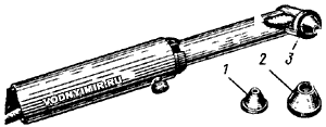
The performance of welding with a stabilized arc showed that to ensure effective protection during welding in the wind, an increase in the consumption of protective gas is required: with a wind of 1.5-2.0 m/s — by 5-10%; with a wind of 2.5-3.0 m/s — by 15-20% or more. With a wind of more than 3 m/s and an increased consumption of protective gas, the weld turns out to be of poor quality, therefore it is recommended to install local shelters in the form of shields, screens, fences, canvas tents, etc.
N. Yakubenko, Candidate of Technical Sciences, «Boats and yachts», 1990.
Specialist comments:
(N. Yakubenko's article is commented by the head of the Welding Department of the Leningrad Shipbuilding Institute, Doctor of Technical Sciences, Professor V. L. Russo).
The author rightly notes the difficulties of welding steel sheets with a thickness of less than 3 mm, saying that for high-quality repairs, it is necessary to carefully select electrodes, and the work should be performed by highly qualified welders with experience in welding thin-sheet structures. In addition to the given electrode brands, others could be recommended, for example, UONIA 13/45, which, when welding at direct current, give very stable results. In fairness, it should be noted that the PS-100-1 converter recommended in the article (undoubtedly a good machine for these purposes) is no longer produced by industry and it is difficult to find it.
The author did not mention the old method of arc welding: welding with a carbon electrode with an independent arc, which is quite simple and makes it easy to adjust the penetration, which is important when welding small thicknesses.
For the repair of aluminum alloy housings, N. Yakubenko recommends the CA-367 burner, designed for welding on installation, which is very appropriate for field conditions. However, the purchase of burners of this type with an autonomous cooling system is very problematic.
The second thing you should pay attention to is the applicability of the proposed welding methods: the recommendations are acceptable for the repair of housings built of welded aluminum-magnesium alloys.
The hulls of motor boats and boats made of alloys such as duralumin (aluminum — copper) riveted construction, it is better to repair with riveting.
It should be noted that the repair of the hulls of small vessels by welding (especially from aluminum alloys) makes sense to organize in repair shops, where for these purposes it is possible to concentrate the necessary equipment and qualified personnel.
The repair of buildings by individual amateurs is in principle possible, but very difficult. Under these conditions, steel housings can be repaired using alternating current arc welding (it is easier to purchase equipment), as well as gas welding with «Baby» type burners.
In the section «Motorboats, boats, yachts — miscellaneous, reviews, tips»
Share this page in the social. networks or bookmark:
