Motor hydrofoil boat «Bottlenose dolphin». Hydrofoil boat design and construction
Leningrad water-motor tourists have long been acquainted with the motor boat «ML», designed by the designer of the shipyard VTSPS M. L. Porzel for the motor «Moscow». This boat served as a prototype for the development of the project offered to the attention of readers. The design of the hull has remained virtually unchanged, but the contours and architecture of the boat have been significantly redesigned.
The «Bottlenose dolphin» hydrofoil motorboat is designed for walking and short (one or two days) hikes along large rivers and ples, where there is a high probability of meeting with developed excitement. With an outboard motor with a capacity of 20-30 hp, the boat can be used as a water skier tow truck for practicing figure skating elements.
| Basic data of a motor boat on wings | |
|---|---|
| Longest length, m | 4,42 |
| Deck width, m | 1,64 |
| Width along the cheekbone on the transom, m | 1,18 |
| Side height amidships, m | 0,68 |
| Body weight, kg | 130 |
| Outboard motor, hp | 14-30 |
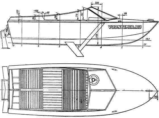
The side profile of the boat is built in accordance with the so-called «trochoid shape» — the shape of the wave profile, which gives the silhouette of the vessel a pleasant soft dynamism, emphasizing its high-speed and seaworthiness. The strongly inclined flat surfaces of the windshield gradually, along a concave curve, decrease in height to the stern, passing into a rigid high cockpit coaming.
The layout of the vessel, the elements of the equipment are no different from the projects repeatedly described in the collection and there is no need to dwell on them in detail. Note only that the seats on the boat are rigid, folding and can be removed into the bow under the deck; the cockpit is completely free and air mattresses or sleeping bags can be laid out here.
The steering wheel is proposed to be positioned on the deck behind the windshield on the port side so that the axis of the steering wheel is vertical. This arrangement facilitates access to the bow under-deck space, simplifies the design of the hull.
In my opinion, in conditions of minor unrest , the greatest efficiency of using a motor boat can be achieved by installing hydrofoils. The speed of almost any planing boat increases at the same time by 1.2-1.3 times or, accordingly, its carrying capacity increases without a significant drop in speed. In particular, there is a case of reaching the wings of a vessel weighing 800 kg under a 20-strong «Vortex».
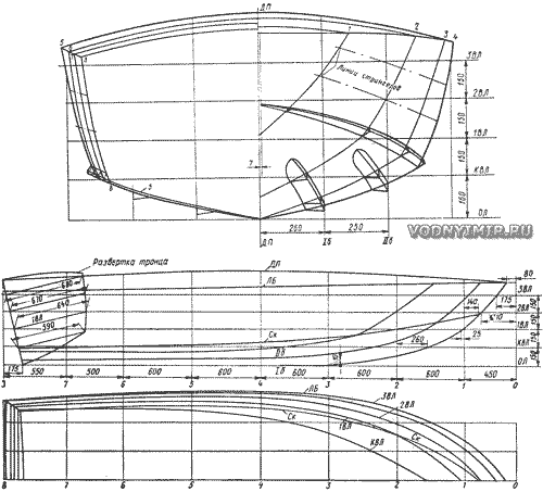
Theoretical drawing of a hydrofoil motor boat
Table of plaz ordinates
| ¹ shp. |
Half-latitude | Heights from OL | ||||||||||
| KVL | 1 vl | 2 vl | 3 vl | board | cheekbone | buttocks | keel | cheekbone | board | deck in DP |
||
| I | II | |||||||||||
| 1 | — | — | 195 | 357 | 350 | 100 | 557 | — | 330 | 415 | 710 | 745 |
| 2 | 145 | 385 | 490 | 565 | 645 | 395 | 222 | 470 | 135 | 315 | 700 | 780 |
| 3 | 405 | 585 | 645 | 697 | 730 | 555 | 90 | 210 | 10 | 240 | 690 | 795 |
| 4 | 542 | 660 | 705 | 745 | 760 | 625 | 65 | 135 | 0 | 195 | 680 | 800 |
| 5 | 600 | 685 | 720 | 760 | 770 | 645 | 52 | 120 | 0 | 175 | 670 | 800 |
| 6 | 615 | 670 | 705 | 730 | 740 | 635 | 51 | 120 | 0 | 162 | 660 | 795 |
| 7 | 600 | 650 | 685 | 710 | 715 | 614 | 50 | 120 | 0 | 155 | 652 | 760 |
| 8(conl.) | 580 | 625 | — | 685 | 690 | 590 | 49 | 120 | 0 | 150 | 645 | 735 |
Constructive longitudinal section and plan of a hydrofoil motor boat
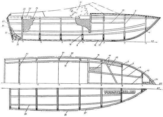
zoom in, 1500x1082, 156 KB
1 — stem, pine, lamin., 50x60; 2 — toptimbers, 20x50; 3 — beams, 20x50; 4 — deck stringer, 15x30; 5 — beam ladder, aviafanera, 4x80x80; 6 — filler, δ=20; 7 — knitsa zygomatic, aviafanera, 4x80x80; 8 — flortimbers, 20x50; 9 — knitsa flora, aviafanera, δ=4; 10, 12, 13 — rack, pad, stainless steel. steel, 2x30; 11 — windscreen, org. glass, δ=5-8; 14 — privalny beam, 20x30; 15 — side stringer, 15x30; 16 — piol support, 20x20; 17 — flor, aviafanera δ=4; 18 — keel; 30x50; 19 — karlengs, 20x30; 20 — glass frame, stainless steel. steel, δ=2; 21 — demi - sims, δ=20; 22 — velvet, pine 20x25 or ash 15x20; 23 — lining, ash, 10x150; 24 — stitching, aviafanera, laminated plastic, δ=2,5-3; 25 — pillow, pine; 26 — zygomatic rebound bar, 30x30; 27 — zygomatic bar, 30x40; 28 — longitudinal redan, oak, 30x60; 29 — bottom stringer, 15x30; 30 — glass fence, org. glass, δ=5-8; 31 — breshtuk, pine, oak, δ=20; 32 — transom trim, aviafanera, δ=6-8; 33 — transom filler, δ=20; 34 — transom interior trim, aviafanera, δ=4-6; 35 — knitsa, oak, laminar., δ=20; 36 — rack, oak, 25x100; 37 — bulkhead skin, aviafanera, δ=6-8; 38 — beams, pine, ash, δ=20; 39 — support of stitching, 20x15; 40 — midway, 15x50; 41 — pillows, δ=20; 42 — pillow under glass, 20x30; 43 — side trim, aviafanera, δ=4-5; 44 — covering of the bottom and deck, aviafanera, δ=5-6.
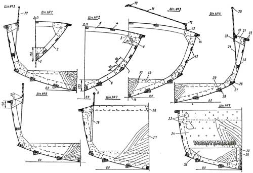
Cross sections on frames
zoom in, 1500x1075, 158 KB
Designations — see on the longitudinal structural section.
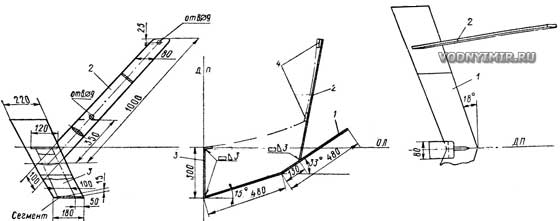
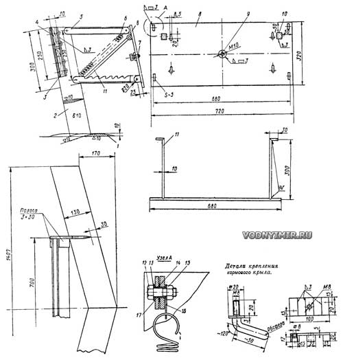
The «Bottlenose Dolphin's» wing device consists of a forward V-shaped wing crossing the surface of the water and a aft flat low-loaded wing. The nose wing is attached to the body with curved bolts, under which washers are placed so high that the handle head is directed downward. If the wing is made of a light alloy, the thickness of the profile should be increased to 0.1 of the wing width. In any case, it is useful to put a bracket resting on the keel, under which the required height of the lining is selected in place. The aft wing is attached to a parallelogram on which the motor is mounted. The design allows you to raise and lower the motor and wing as needed. The springs are selected in such a way as to balance the weight of the motor with the wing, and then the system is held in the lowered state only by the screw stop.
Nose wing design
zoom in, 1500x579, 62.5 KB
1 — wing, blank 15x220; 2 — side rack, 10x80; 3 — middle rack; 10x100; 4 — wooden linings.
Aft wing design
zoom in, 1500x1573, 197 KB
1 — wing, 10x130; 2 — rack 10x100; 3 — engine board; 4 — screw M4x60; 8 pcs.; 5 — bracket lever (square with a cut shelf); 6 — spring; 7 — bolt M10x20; 8 — plate δ=3; 9 — sleeve Ø 40x5; 10 — tube Ø 20x5, L=30; 11 — stop, weld from a bar Ø 10 mm; 12 — bolt M10x30; 13 — washer 10; 14 — washer 14; 15 — nut M10; 16 — spring earring, δ=2; 17 — bushing Ø 14x1.5, L=13.5, brass.
Only the simplest option of attaching the wings to the body is given here. A more successful, but also more complex system is described by A. S. Chugunov in the collection No. 26 (1970). The angles of installation of the wings are selected by successive approximation, but for the first exit, the nose wing must be installed with an angle of attack to the horizon minus 1-2°, the stern +1°.
Fuel tanks (we recommend using standard tanks for the «Neptune» engines) are installed behind the aft waterproof bulkhead, then in case of accidental splashing of the mixture, gasoline and oil do not get into the cockpit. It should be borne in mind that the boat will go planing faster with a more forward alignment, and after overcoming the resistance hump, the load can be shifted to the stern — this will have little effect on speed.
A few words should be said about the contours and propellers. The Bottlenose Dolphin is a typical vessel with a «deep V», but to improve the strength and hydrodynamic qualities of the hull, the bottom branches of the frames are given a significant bulge. At low speeds, the boat behaves like an ordinary keeled boat: blows on the strongly keeled bottom at the cheekbones are not great, but at full speed with a small load, the boat goes on an almost flat, strongly elongated section of the bottom with optimal angles of attack and is not sensitive to changes in alignment.
In the first approximation, you can pick up a screw using the recommendations of the given table (the motor «Vortex-M»):
| Load | Screw pitch, mm | Diameter, mm |
|---|---|---|
| On the wings | ||
| 2 people. | 380 | 240 |
| 4 people. | 300 | 240 |
| Without wings | ||
| 2 people. | 280 | 240 |
| 4 people. | 220 | 240 |
| 1 person. + 1 water skier | 240 | 240 |
Three-bladed propellers with a disc ratio equal to 0.55 are recommended.
In conclusion, we note that the stem should be glued together from rails 6-8 mm thick, and after processing it should be docked with the keel at a length of at least 300 mm. Fasteners made of non-ferrous metals can be replaced with ordinary steel, but oil paint should be poured into the holes for screws and bolts. VIAM-B3 glue can be replaced with epoxy adhesives or K-17 glue, sometimes called «synthetic carpentry», for which oxalic acid is used as a hardener.
Housing motor boats are recommended to be pasted with fiberglass and painted with epoxy enamels. In the absence of such enamels, pentaphthalic enamels or oil paints are used, but the case will have to be sanded beforehand.
VIAM-B3 glue can also be used to cover the bare body, but then 10-15% alcohol and 3-4% acetone are added to it. This composition penetrates well between the fibers of wood and reliably preserves it. During polymerization, the adhesive film is stretched and the surface is smooth and shiny. Over time, the coating acquires a dark cherry color.
Boat projects for self-construction
Share this page in the social. networks or bookmark:

