How to build a fiberglass boat
| *«Bruce Roberts Designs» — this company is well known to amateur shipbuilders of all continents. Design bureaus of the firm that develop drawings of small vessels of various purposes and types and the technology of their construction at «home shipyards» are available in the USA, Canada, England, Australia and New Zealand. As a rule, amateurs are offered standard projects that have been well tested by the construction of many copies of ships. In the catalog of the company in 1989 there were about 50 projects of boats and yachts, and most of them can be built in various versions — from fiberglass, steel, aluminum or wooden construction. Each project contains from 20 to 30 sheets of large-scale drawings with specifications and recommendations for the construction of the vessel. At the request of the customer, life-size plasma drawings of frames, drawings of homemade tools and accessories for assembling the hull, three sheets of drawings for making practical things, devices for automatic control of a sailing yacht, etc. can be sent. The cost of a set of drawings ranges from $ 49 for a 5.7 m long shvertbot project to $750 for an 18-meter seaworthy yacht project. During its existence, Bruce Roberts Design has sold over 3,000 sets of drawings; the company has information about 500 yachts and boats built according to its projects. Some of them have traveled around the world; two yachts participated in the transatlantic races of single yachtsmen OSTAR. In many cases, vessels designed by Bruce Roberts are also used for commercial activities — as fishing, for charter tourist flights. |
From the editorial office: This article introduces the method of independent construction of small fiberglass vessels recommended by Bruce Roberts-Hudson* for the hulls of boats and yachts of relatively large dimensions (7.5-18 m long). For example, for the construction of the boat «WAVERUNNER-285», drawings of the general location and a sketch of the contours of the hull of which are given here. This is a fairly seaworthy gliding boat that can be used for sea trips and tourism. The vessel has a raised freeboard and a considerable width, which makes it possible to place a comfortable lounge with a galley and toilet in the bow, and a double sleeping cabin in the stern, under the cockpit. The control post is located above the engine compartment; it is protected by an inclined windshield, which creates a wind shadow also in the aft cockpit, equipped with soft sofas.
Due to the large width along the cheekbone, the boat has high stability in the parking lot, and the increased keeliness of the bottom in the stern contributes to a soft ride on excitement. All the sheets of the outer skin are easily unfolded to the plane, therefore, waterproof plywood can be used for the skin. The drawings are designed in two versions — plastic and wooden construction.
| Basic data of the boat «WAVERUNNER-285» | |
|---|---|
| Longest length, m | 8,73 |
| KVL length, m | 7,33 |
| Maximum width, m | 3,05 |
| Draft, m | 0,51 |
| Engine power, hp | 250-500 |
| Speed, km/h | 28-56 |
General view of the boat, the construction technology of which is discussed in the article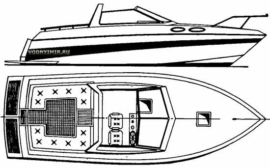 |
General location of the boat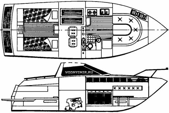 |
Outline of the hull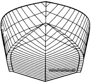 |
The boat is designed to install one or two engines with a total capacity from 250 to 500 hp with a direct reverse gear, which allows you to reach speeds from 15 to 30 knots (28-56 km/h). Propulsion systems with angular rotary-folding columns or powerful outboard motors can also be installed on the boat.
This boat is also called the «Scandinavian Express» — thousands of similar family boats surf the waters of traditional holiday destinations of Swedish, Norwegian and Danish yachtsmen.
The experience of foreign amateur shipbuilders shows that a ship built independently costs the owner 50% and even 75% cheaper than one purchased from a shipyard. But the main incentive for many amateurs remains the joy of creativity and knowledge of the subtleties of various professions that a small ship builder needs to master.
The proposed technology for the construction of fiberglass boats is not the last word in small shipbuilding — it simply reflects the experience gained by many amateur shipbuilders during the independent construction of single vessels or a small series by the combined owners. The method provides for the manufacture of the necessary equipment with minimal cost of materials and labor and is most suitable for the construction of boat hulls up to 18 m long or yachts with simplified contours, the outer skin of which unfolds on a plane.
As with the construction of ships from other materials, it is necessary to start with the breakdown on a plywood board or a sheet of cardboard of theoretical frames and a full-size outline of the stem. The shield or plaz should have a width equal to the width of the housing under construction plus 300 mm; its height should be greater than the height of the housing by about 400 mm. This will allow you to assemble the transverse patterns of the frames and the stem directly according to the plasma breakdown. The upper ends of all frames must be extended to a certain height, which is represented on the plaza by a horizontal line perpendicular to the DP line and called the shergen line. The position of this line should be chosen taking into account the fact that after assembling the matrix for molding the body, it will have to work in it and it is important that the shergen bars located at the top do not create inconveniences. Shergen-slats significantly simplify the installation of patterns based on the matrix and checking the correctness of the contours.
When laying out patterns, it is necessary to take into account the thickness of the slats and sheet material with which the inner surface of the matrix will be sheathed. That is, it is necessary from the theoretical line of each frame to put aside the mentioned sum of the thicknesses of the slats and sheathing and already cut out the details of the patterns according to this marking and assemble them. To transfer the line from the plaza to the material, you can use tracing paper or, having laid out the nail caps along the line, put a blank on top and press it to get impressions of the hats on the wood (see, for example, p. 132 books «15 projects of vessels for amateur construction», 1985, L-d, «Shipbuilding» — ed.).
Individual parts of the transverse patterns are connected using linings and knits made of pieces of plywood 8-10 mm thick, if we are talking about a body about 10 m long. It is better to glue the pads to the patterns and fix them on nails or screws. When setting up the linings, it should be taken into account that later it may be necessary to remove the small from the edge of the pattern, so the edges of the plywood and metal fasteners should be placed at a sufficient distance from the working edge of the pattern.
Before assembling the patterns into a matrix, it is worth thinking about the convenience of molding the outer skin. To this end, it is necessary to provide for the possibility of tilting the matrix on both sides so that it is possible to work standing side by side on the floor, or to fix two large-diameter round rims on the matrix, which will allow it to be turned into any position by rolling on the floor. In any case, the matrix should be a sufficiently strong and rigid structure so that the shape of the housing provided for by the project is not distorted during construction. Large matrices are assembled on longitudinal beams forming a horizontal base, bridges are mounted inside for the convenience of work on gluing the housing.
Having installed the longitudinal bars of the matrix base, it is necessary to mark the position of all the patterns on them and pull along the steel wire — string indicating the DP of the vessel. The second string can be stretched at the height of the shergen line. On the shergen-bar of each pattern and on its bottom part, the risks of DP should be outlined in advance, according to which each pattern is installed on the base. At the same time, with the help of a plumb line, the verticality of each pattern is controlled, and to control their perpendicular to the DP of the vessel, you need to make a large carpenter's right triangle. At the same time, the stem pattern is also installed.
The patterns of frames located in the nose from the midsection frame are recommended to be placed on the marking line so that the bow edge of the pattern coincides with this line, and the stern patterns are combined with the theoretical line of the frame with their stern edge. In this case, it is possible to avoid malkovka patterns or significantly reduce its volume when lining the matrix with longitudinal rails.
Construction of the matrix for the manufacture of the plastic hull of the boat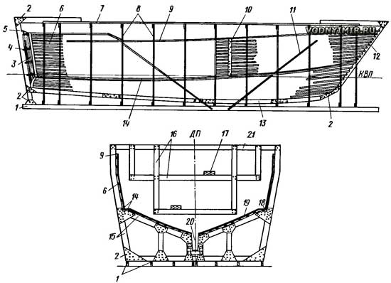 1 — longitudinal beams of the base; 2 - plywood knits; 3 — transom stitching with slats; 4 — transom cross-section templates; 5 — transom rack in DP; 6 — sewing rails; 7 — upper slipway at the level of the shergen line; 8 — patterns on frames; 9 — rail along the upper edge of the side; 10 — plywood lining in the intervals between the patterns; 11 — slant; 12 — stem pattern; 13 — keel pattern; 14 — slats that form the cheekbone; 15 — pattern boards along the frames; 16 — beams of suspended scaffolding; 17 — flooring used in molding the hull; 18 — the radius of rounding of the cheekbone, formed with the help of epoxy putty with filler; 19 — sheet material (plywood, hardboard); 20 — recess for the keel matrix; 21 — shergen-the bar of the pattern. |
Breakdown of matrix patterns on the plaza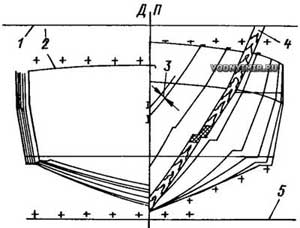 1 — the shergen line; 2 — the sweep of the convex transom sheet; 3 — the size that should be postponed outward from the outline of the theoretical frame (the thickness of the matrix sheet stitching plus the thickness of the slats); 4 — the pattern; 5 — the main line. |
It is best to start installing patterns from the midsection frame. After making sure that this pattern is placed vertically and perpendicular to the DP, secure it securely to the base bars, put the braces in order to use it as a base for installing patterns of other frames. Having installed all the patterns, including the stem pattern, and the rack located in the transom DP, loosening them with braces to exclude any movement, you can proceed to lining the inner surface of the matrix with longitudinal rails.
For this purpose, slats with a thickness of 12-15 mm and a width of 50 mm are used. Slats up to 100 mm wide may be more convenient for the bottom. The length of the rails should exceed the length of the body by 100-150 mm for ease of fitting. First, two slats are installed along the cheekbone — one is allowed on the side, and the second on the bottom. Then they put slats on the upper edge of the side. The extra ends of the rails are released aft of the hull — they are used when installing the transom. If the transom has a perch, then you need to install one or more templates located across the transom and fixed to the rack in the DP. Then the surface of the future transom is sheathed with vertical slats. Usually there is no need to fasten the side and transom rails together — it is enough to put plywood linings outside near the place of their docking to get a smooth interface of the surfaces. It would not be superfluous to check the correctness of the transom outline by attaching to it from inside the matrix a template cut out of cardboard according to a theoretical drawing.
| Construction of stringers with single-layer cladding: a — decorator (can be made of one or more foam bars, depending on the size of the cross—section of the stringer); b — a typical cross-section of the stringer in the form of a trapezoid; c — deck shelf (internal anchor beam); d — foundation beam for the engine. 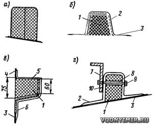 1 — styrofoam decorator; 2 — gluing of fiberglass layers; 3 — outer skin; 4 — bulwark; 5 — «wet square»; 6 — shelf molding to the side skin; 7 — foundation square; 8 — metal sleeve that prevents the foam from crumpling under the bolt; 9 — bolt; 10 — rubber gasket. |
With another method, you can assemble the transom matrix in the form of a separate node and then mount it in its place. Simultaneously with the transom lining with slats, the rails are placed on the sides and bottom of the matrix. In order to avoid skewing the matrix and twisting the body, the slats should be placed alternately from one side and the other, hammering nails into the edges of the patterns. When all the slats are installed, transverse strips of plywood with a thickness of 10-12 mm are placed on them from the outside, which provide a connection between all the slats and smooth contours in the intervals between the patterns. One part of the stripes is located from the cheekbone to the keel, and the other — from the cheekbone to the upper edge of the side. The slats are attached to these strips with nails, which are hammered through each rail. At the same time, one person hammers nails, and the second supports the plywood bar from the outside with a massive block to ensure a tight connection of the rail with the overlay.
After making sure that the contours indicated by the slats are smooth, you can proceed to the internal stitching of the matrix surface on top of the slats with sheet material — three-four-millimeter plywood, hardboard, etc. The sheet material should be glued to the slats with any glue, for example, bustilate and try to use as few nails as possible. Their heads leave a mark on the surface of the body removed from the matrix, and their putty requires a lot of effort. The sewing sheets should be placed sequentially, in small sections. Having adjusted one sheet in place, cover the surfaces of the slats adjacent to it with glue, then put the sheet in place and press it with sandbags, bricks, etc. The joints between the individual sheets are carefully adjusted and after the glue hardens, putty. Epoxy putty is also used in all interfaces in order to perform them along the radius along which the glass material reinforcing the cladding can fit.
| Structural components of the housing set with a three-layer skin: a — deck shelf; b — deck connection, with a side without a bulwark; c — installation of the deck panel on the shelf; d — molding of the deck and bulwark; d — section along the cheekbone 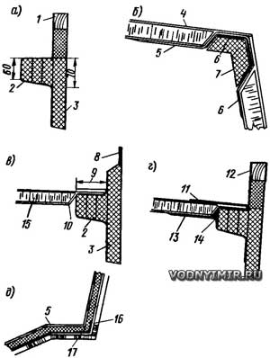 1 — wooden filler; 2 — shelf decorator made of three bars of foam; 3 — hull lining; 4 — outer layer of fiberglass; 5 — inner layer of fiberglass; 6 — «wet square» — molding of the deck to the board; 7 — foam liner; 8 — transition of three-layer lining of the side into the bulwark; 9 — the width of gluing the inner and outer layers of fiberglass of the three-layer deck; 10 — beveling of the edge of the deck panel at 45°; 11 — molding with a width of 100 mm; 12 — gluing the bulwark with fiberglass; 13 — «wet square» with a shelf width of 125 mm; 14 — epoxy putty with filler; 15 — filler of a three-layer deck, balsa; 16 — matrix; 17 — reinforcing layers along the cheekbone. |
The quality of the matrix surface finish also depends on the quality of the outer surface of the future housing. Therefore, the surface of plywood should be carefully plastered, sanded, and then painted with two or three layers of pentaphthalic paint. Before the last layer, it is good to sand the «wet» surface with a fine waterproof sandpaper. It should be remembered that any negligence in the preparation of the matrix will be manifested by the corresponding defects on the finished case.
The day before forming the outer skin, the surface of the matrix is covered with a separating layer, which prevents the laminate from sticking to the matrix. As this layer, amateurs most often use floor wax, wax, vaseline, etc.
It is very important to ensure good quality of the decorative (painted) binder layer and the first layer of fiberglass. If the housing is built under a canopy, they should be applied in warm, dry weather at a temperature of 20-25 °C and humidity of no more than 65%. The decorative layer is applied with a brush or spray gun, its thickness should be within 0.4-0.6 mm. Even if it is planned to paint the body with paint in the future, it is recommended to apply a layer of unpainted resin anyway — it will give the surface of the cladding glossiness, smooth out the texture of fiberglass, which manifests itself in fiberglass.
It is best to work on the molding of the body to conduct two or three people. When building a boat with a length of 10-15 m in one day, it is recommended to apply no more than two layers of laminate to avoid deformation of the matrix or detachment of fiberglass from it. As the first layer, a thin fiberglass fabric is laid, which is carefully rolled with rollers to the surface of the matrix. It is very important to exclude the appearance of air bubbles, which will create a lot of problems after removing the finished hull from the matrix and in the further operation of the boat.
Laying two layers of glass material per day is a kind of form of temperature control and ensures high quality fiberglass. Working in this way, two people can glue the hull of a 15-meter boat in a few days.
Cross-section of the matrix according to the stem pattern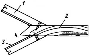 1 — matrix stitching rail; 2 — stem pattern; 3 — sheet material; 4 — radius rounding (epoxy putty with filler). |
The number of layers and grades of glass materials are usually indicated in the drawings. After the required number of layers is laid over the entire surface of the hull, additional layers are glued along the keel and in other places indicated in the drawings. The rule should be observed that the edges of the glass material layers overlap each other on the cheekbone, keel and edges of the transom and along the length if short pieces are used. Every day it is necessary to cut off excess fiberglass along the upper edge of the side no later than a couple of hours after the end of gluing the next layers, when the binder is gelatinized. You should not leave this operation for another day, because the «obloy» will have to be sawed and, in addition, it creates inconveniences for the molding of subsequent layers.
If the housing of a three-layer (sandwich) structure is being built, then before placing the filler plates, it is necessary to lay all additional layers of glass material. The best method of gluing foam in such structures is the «vacuum bag» method, in which a rubber cloth is laid on the surface of the foam, sealed along the edges and then air is pumped out from under it using a vacuum pump.
Cross-section of the matrix with a body made in it with a longitudinal set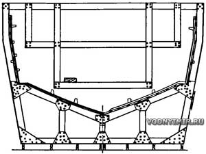 On the right is a sandwich construction housing, on the left — with a single-layer skin. |
Atmospheric pressure tightly compresses the «bag» and with it the laminate. The single-layer cladding is necessarily reinforced by a set system consisting of stringers, frames, floors and bulkheads. With three-layer cladding, it may be necessary to install stringers and frame frames, as well as stiffeners in certain places. Stringers and frames usually have an identical design, consisting of a foam filler of the required cross-section and fiberglass gluing. Usually, longitudinal stringers are first installed on the skin, then split (or inter-wall, as shipbuilders sometimes call intermittent connections) frames are glued between them. Usually the frames go from the upper edge of the side to the lower stringer, which serves as a support for the payoles. It is recommended to first put the foam decorators of all the beams of the set, and then paste them over in one step with fiberglass strips. Of course, accuracy is required when moving inside the case with the supplied decorators, so as not to move them from their place. To accelerate the curing of the binder, which is used for gluing decorators, local heating can be used with small electric lamps.
To simplify the work, it is desirable to use foam plates with a thickness equal to the height of the stringer profile or frame, cutting bars of the maximum possible length from it on a band saw (in its absence, you can do this work with a hand hacksaw). Then the side edges of these bars are processed to a trapezoidal cross-section, if necessary, the base is adjusted along the bottom outline. The cross-section of the kit parts may vary depending on the role performed by the connection and its location in the housing. For example, the stringer support of the floor should have a flat upper edge on which the plywood flooring is laid, and the side edge is cut off to fit snugly to the outer skin. Thus, this stringer can have a triangular cross-section. The longitudinal beams of the engine foundation can have vertical walls on the inside and inclined, facing the sides. The individual bars of the connections of the set are joined together on an epoxy binder.
Deck matrix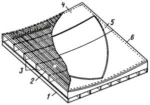 1 — 60x100 base bars; 2 — 20x51 slats; 3 — deck die patterns; 4 — matrix sheet coating, plywood, hardboard; 5 — adhesive tape — limiter of the contour of the molded deck panel; 6 — fixing sheet material with nails along the perimeter of the matrices. |
For gluing stringers and frames, glass wool and fiberglass are used. In some cases, in order to obtain the effect of a T-section beam, which is more durable and rigid when bending, additional layers of reinforcing material are laid along the upper edge of the stringer. The width of the molds adjacent to the housing can be different — from 40 to 120 mm — usually these details are indicated in the drawings of the buildings.
Frame floras and semi-columns are used to reinforce the bottom and install various equipment. Semi-columns can be made of water-resistant plywood or pre-molded flat fiberglass sheets, which are then adjusted along the contours of the body and attached to the skin with the help of «wet corners» — L-shaped molds made of several layers of fiberglass. The bottom stringers and, first of all, the foundation beams of the engine should be installed in place first. This work must be carried out with all care, since the correct location of the motor in the housing and the subsequent installation of the shaft line depend on it.
Body cross section 8.5-meter boat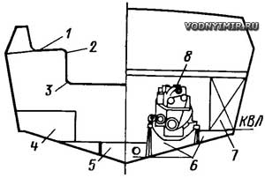 1 — a seat molded according to a special matrix; 2, 3 — a 50 mm radius rounding; 4 — a fresh water tank bed; 5 — reinforced flora; 6 — foundation brackets for the engine; 7 — fuel tank; 8 — engine. |
Transverse bulkheads are installed when all stringers and frames are glued in. Most often they are made of one or two layers of plywood, and two-layer ones are most often used if the width of the plywood sheet is not enough to cover the entire width of the boat. The bulkhead is molded to the body on both sides with «wet squares» with shelves about 100 mm wide. To strengthen the connection at the edge of the bulkhead along its perimeter, it is recommended to drill through holes with a diameter of 30-40 mm with a distance of about 150 mm between the centers, then chamfer the edges of the holes and then perform molding. In the edge of the bulkhead, a sheet pile can be selected according to the thickness of the fiberglass molding so that the connection becomes invisible after painting the bulkhead. Some builders attach bulkheads to the frames molded to the body with bolts. In the open part, all these connections and bolts are closed with decorative wooden slats. It is recommended to make the main bulkheads at their full height, including parts protruding above the deck. This will simplify the production of the cabin and deck in the future. Reinforced floras are installed in the span between the bulkheads, and additional ones are placed in the engine compartment in order to more reliably loosen the longitudinal beams of the foundation under the engine and support fuel tanks, which are most often installed at the sides. By the way, it is necessary to warn against the device of fuel tanks built into the fiberglass housing. As a rule, such containers are not sealed, and finding and eliminating leaks during the operation of the boat is a difficult task. It is best to make these tanks plug-in and carefully test the tightness of the liquids for which they are intended before installation in the boat.
Additional reinforcements are installed under the helm and steering gear, pumps and latrine. After that, it is recommended to cover the entire inner surface of the case with a layer of binder, it is possible with pigment.
At this stage, before manufacturing the deck and superstructure, it is advisable to install the most bulky equipment in its place — the engine, fuel tanks, fresh water tanks, etc. It is better to postpone the installation of pipelines and on-board power grid for the period when the deck and superstructure will be installed. For single and small-scale construction of boats, the deck and superstructure are assembled on site from pre-made fiberglass sections — panels and individual parts. There are two possible deck designs — single-layer or sandwich, with a light filler between the outer and inner layers of fiberglass. The three-layer deck has a number of advantages, for example, it well thermally insulates cabins from the external environment due to a layer of foam, has high rigidity and strength with a minimum number of beams set. The single-layer construction is more suitable for large workers and fishing boats, where a heavy and complex sub-deck set system is required, taking heavy loads from deck equipment.
Section of the hull of a 12.5-meter boat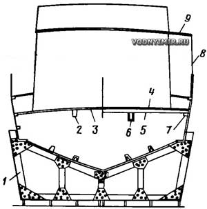 1 — matrix; 2, 6 — carlengs; 3 — fiberglass deck; 4 — removable plywood flooring over the engine compartment; 5 — wooden beams; 7 — shelf; 8 — cabin wall, made of fiberglass, made in a flat matrix; 9 — cabin roof, made in a deck matrix. |
As a lightweight filler for a three—layer deck, rigid foam or end sections of balsa wood are used (balsa is not used in domestic shipbuilding, because it is an exotic material that is inaccessible even for shipyards — ed.). The drawings of the vessel indicate the thickness of the filler, as well as the system of the deck set. Usually, on boats up to 12 m long, beams alone are enough, and the decks of ships of greater length are also supported by a pair of longitudinal ties — carlengs.
When starting to make a deck, it is necessary to cut out a template and a counter-template of beams from a wide board, the length of the width of the hull. Using this template, a matrix is made for gluing the deck and roof panels of the cabin. The width of this matrix is equal to the maximum width of the boat hull along the deck, the length is 300-400 mm longer than the longest deck panel. For boats up to 18 m long, a matrix with a length of about 5 m is sufficient. The deck matrix is made without the saddle of the side line — it is recommended to put the molded panel in the hull at a time when the plastic has not yet fully hardened and can be easily bent according to the saddle of the side, if there is one.
The matrix is manufactured in the same way as for the main body. First, several transverse patterns are assembled, for marking which a counter-pattern of the beams is used. The patterns are installed on longitudinal bars (like the patterns of frames), they are securely fixed and sheathed first with slats, then with sheet material, which is put on glue, fixing with nails only along the outer edges. The surface of the matrix is putty, sanded and painted.
Several temporary beams are inserted into the hull of the boat in those places that are supposed to be closed by the deck. Using strips of plywood fastened with nails, the deck flooring templates are removed from these places, transferring the outlines of the side line to them. Usually such templates are made only for one half of the DP panel, because the second half of the other side is symmetrical. Then the template is laid on the deck matrix and the contours of the future flooring panel are limited using sticky tape glued to the surface of the matrix. Next, a separating layer (wax, wax, etc.) and a decorative (or unpainted) binder layer are applied to the designated area of the matrix.
To prevent the panel from warping, no more than two layers of laminate are glued daily. After the gelatinization of the last layers of fiberglass, the panel is removed from the matrix and transferred to the housing until the plastic has finally hardened. Here the panel should have sufficient support in the form of temporary beams installed after 0.8-1 m, and one or two longitudinal rails embedded in them. It is important that the deck panel does not receive an unplanned deflection.
The sub-deck set provided for by the drawings of the boat is made similarly to stringers and frames, while the panel is still in the matrix. Then the inner surface of the panel is covered with a layer of painted or pure binder. At the same time, it is necessary to avoid getting this binder into places that will be molded to the main body or structures of the cabin. If the deck is of a three-layer structure, then the filler along the edges of the panel should be cut at an angle to form the bearing layers of fiberglass to the sides. All deck panels are molded from the outside and from the inside, and the width of the molding is 75-100 mm from the junction. Some of the molding layers can be made narrower to avoid excessive thickening at the edges of the «wet square». It is necessary to carefully remove all traces of the separation layer from the fiberglass surface at the molding sites, as well as from the rest of the panels before painting them.
The side walls of the cabin can most often be glued on flat matrix tables and assembled on the deck into a single structure using «wet corners».
In conclusion, it should be recalled about safety when working with fiberglass, the components of which are far from harmless to health. You need to work in rubber gloves, use protective masks when molding and especially when scalding.
Using the described technology, an amateur shipbuilder can build a boat for less than 50% of the cost of a finished vessel of the same size and quality built at the shipyard.
Boat projects for self-construction
Share this page in the social. networks or bookmark:
