Dimensions and contours of the displacement boat
In recent years, in our country and abroad, the interest of water lovers in slow-moving, but also the most economical displacement motor vessels has reawakened. The increase in operating costs, difficulties with the purchase of gasoline on the banks of most of our rivers force many owners of planing motor boats and boats to keep their vessels for most of the season on a joke or use them with obviously low-power and not corresponding to the hull motors, adapt sails. It is not by chance that «leisurely» boats with old four-stroke engines of the «L» series and with various diesels have risen in price.
Unfortunately, in general, the industry cannot offer a single displacement boat with an economical stationary engine. This is explained by an obvious and simple reason: engines with a capacity of 6-40 hp, adapted for installation on boats, are not produced by motor builders. At the time of the craze for high speeds on light planing boats with then-new outboard motors with a capacity of 20-25-30 hp, the less powerful «SM-255L», «SM-500L», and «Luch» that were already on the conveyor ceased to be in demand; more than ten years ago, all these boat engines were discontinued.
Unsurprisingly, now amateur shipbuilders have to not only create boats with their own hands, but also independently adapt random general-purpose engines to work on these boats — old «starters» of tractor diesels, motors from portable power plants, compressors, pumps, etc.
Be that as it may, but today economical, comfortable displacement boats are being built and operated in many basins of the country. Unfortunately, the boat built independently and according to its own design does not always justify the builder's hopes. The fact is that competently designing a displacement vessel is not at all easier than a high-speed, and this truth is far from so obvious.
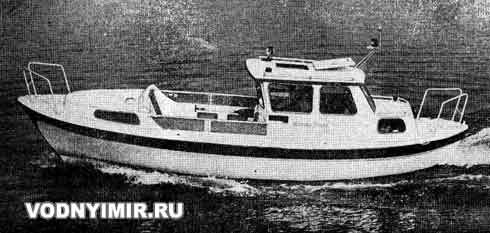
Displacement plastic tourist boat «Murski-Jeanne 800» built by the Finnish shipyard «Beaufort».
Length — 8m; width — 2.45 m; draft — 0.85 m; passenger capacity — 5 people. Engine — diesel with a capacity of 12-25 hp; speed — 13-15 km/h.
In many cities, such popular «aksayki», «finki», «kayuki» and other boats of local types have already been forgotten 20-25 years ago, the contours and dimensions of which were developed over a number of decades as optimal for swimming in this particular reservoir on oars, under sail and low-power motors. Amateur shipbuilders often copy the «newfangled» models of duralumin and plastic boats, which are designed not for displacement and not even for transient mode, but for pure planing — movement at a much higher speed, which can be achieved only with an engine many times more powerful than those put on these boats in the hope of saving fuel.
We emphasize that the economic effect can be obtained only if the hull of the boat is built taking into account the hydrodynamics of leisurely sailing. Let's consider its features.
An ordinary planing boat, such as the «Progress», glides through the water without touching it with the stem, waves diverging from the sides break out from under the bottom somewhere near the middle of the hull length, and the entire transom, starting from the bottom, is not washed with water. At a lower speed, the same hull sits in the water for the entire length of the keel, the draft increases, the trim on the stern decreases — the transom is submerged in water. The nature of the water flow around the hull is also changing. The boat becomes poorly streamlined: a breakwater rises in front of a blunt, not designed for such a mode of movement; behind the transom pressed into the water, vortices and an area with reduced pressure are formed, which seems to «suck» the boat back. A certain (and considerable) part of the propeller stop is spent on overcoming these forces of resistance to the movement of the boat that appeared with a drop in speed. Summing up with the increased friction resistance of the skin against the water (after all, the wetted area has become much larger!), these forces, even at the lowest speed of movement, consume a significant part of the power developed by the engine.
With increasing speed, the power costs for creating a whole system of waves formed at the hull of a moving vessel begin to play an increasingly important role. The reason for the occurrence of these waves is easily explained: pressure changes occur in the layers of water adjacent to the moving body, the free surface of the liquid under the influence of these pressure forces is deformed — rises in areas with increased pressure, and falls where it is below static.
The first area of increased pressure is the area adjacent to the stem. Here the crest of the bow wave — a breakwater is formed. At an angle to the direction of movement, waves diverge from the stem, and are called divergent. At higher speeds, transverse waves become discernible along the sides; their first crest is usually located at the very stem. As you move away from the stem, the hull of the vessel usually becomes wider; water particles, by virtue of this, accelerate their run, respectively, the pressure in the water layers near the hull decreases. This local pressure drop manifests itself in the form of a depression — the sole of the wave formed behind the widest section of the body. It gives rise to the aft transverse wave. Astern, you can also notice a second — aft — system of diverging waves.
Shipbuilders often use not the absolute, but the relative speed of the vessel, called the Froude number in the calculations of the seaworthiness of ships:
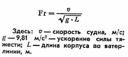
Below we will see that the choice of this expression is not accidental: it includes the same quantities that determine the wavelength during fluctuations of the water surface, And each value of the Froude number corresponds to a certain and always constant character of wave formation due to the wavelength.
It is the waves, and first of all, the transverse waves, that at certain speeds determine the power that the engine must develop in order for the boat to reach this speed. The energy spent on creating and maintaining waves at the hull of the vessel during its movement is estimated by the value of the wave resistance. At a relative velocity Fr=0.5, the wave resistance is 60-65% of the total value (sum) the forces of water resistance to the movement of the vessel. It is clear, therefore, that the designer, when developing the design of any displacement vessel, should pay special attention to reducing the wave resistance — to give the hull a shape (contours) and dimensions optimal for a given relative speed. The amount of energy absorbed by a transverse wave is proportional to the wavelength and the square of its height. There is a relationship between the wavelength and the speed of its propagation:

It is obvious that the waves created by the hull move at the same speed as the boat itself. Using the above dependence, you can calculate the wavelength for any speed of the boat. For example, for a speed of 6 km/h, the wavelength will always be 1.78 m; for 8 km/h — 3.16 m; 10 km/h — 4.95 m; 12 km/h — 7.10 m; 14 km/h — 9.66 m; 16 km/h — 12.64 m; 13 km/h — 16.0 m.
Note that the wavelength does not depend on the dimensions of the vessel (after all, there is no L value in the formula!). When, say, a 300-meter liner and a 6-meter boat go at the same speed of 14 km/h, a transverse wave of the same length occurs near their hulls — 9.66 m. (The height of the wave is another matter — it depends on the displacement of the vessel and near the liner will, of course, be much higher). But there is a significant difference in another. If 30 waves fit on the length of our liner, then the second crest of the bow transverse wave from the 6-meter boat will be almost 4 m behind its stern...
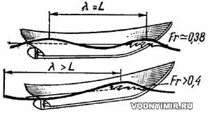 In other words, such a boat at a speed of 14 km/h will be similar a carriage trying to enter a hill that is moving away from it at the same speed. At the same time, the boat acquires a strong trim on the stern and the water will flow around it not at all along the smooth waterlines that the designer depicted. It will be necessary to significantly increase the power supplied to the propeller and give the stern of the boat full and flat-bottomed contours so that the hydrodynamic forces lift the stern and the boat can «drive» to the crest.
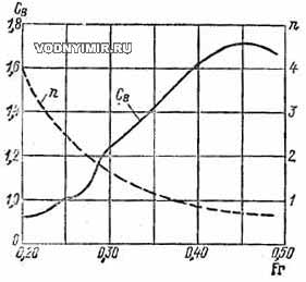 Dependence of the wave drag coefficient C and the number of transverse waves formed at the hull of the boat, depending on the relative speed Fr. |
On the graph of the dependence of the power costs on the propeller shaft on the speed of the boat, this area of «climbing the hill» is expressed as a sharp upward rise of the curve at Froude numbers about 0.45-0.52. And at Rg=0.9-1.2, a hump corresponding to the maximum resistance appears on the power curve. If the vessel is able to overcome this «hump», it will be able to continue moving at high speeds already in a new mode — planing mode.
The conditions for overcoming the hump and switching to the planing mode are well known: this is a large specific engine power (at least 35 hp for every 1 ton of displacement) and special hull contours. However, today we are interested in much lower speeds corresponding to the regime of displacement navigation, and not planing. This is the area of the graph where the curve of the required power is just beginning its steep upward climb, i.e. the relative velocity does not exceed the values of Fg=0.38-0.42. Here, if we continue to talk about a 6-meter boat, each additional kilometer of speed requires an increase in engine power by 1.5 or even more times.
Therefore, we can formulate the limiting condition as follows: our displacement boat must sail not on one crest of a transverse wave, but at least on two crests of neighboring waves. In other words, the wavelength generated at the estimated speed of movement should be no more than the length of the vessel along the waterline.
If we now turn to the above figures characterizing the dependence of the transverse wave length on the speed of the boat, we can conclude that our boat with a length of 6 m can go on two or more crests at a speed of up to 11 km/h, a boat with a length of 8 m — up to 12.5 km/h, etc. for movement with such speeds, only 3.5-4 hp of power is required for every 1 ton of displacement, i.e. 8-10 times less than for movement in the planing mode!
The effect of length on speed can be illustrated by such an example. Two lifeboats were built, on which the same diesel engines «4CHSP 8.5/11» with a capacity of 23 hp were installed. The boat «SSHAM22» with a capacity of 22 people had a length of 6.5 m along the waterline and a displacement of about 4 tons. The second boat «SSHPM90» was 90-seater, had a length of 10 m and three times the displacement — 12 tons. However, during tests with a full load, the boats showed, strange as it may seem, almost the same speed: «SSHAM22» — 12.1 km/h, and «SSHPM90» — 11.5 km/h. Now the solution is already clear to us! The first boat had an extremely unfavorable ratio of the length of the hull and the wavelength formed at a speed of about 12 km/h — it was on the same crest. But on the 10-meter length of the «SSHPM90» two ridges were laid, it went without trim in the optimal and most economical mode of displacement navigation.
A successful correspondence of the dimensions to the speeds can also be found on boats of local types developed by practice: most often they are built with a length of at least 5.5-7 m. Large, heavy fishing boats unexpectedly turn out to be surprisingly light on the move — when rowing, even when compared with 4-meter pleasure boats. In a word, having a low-power engine, it is necessary to build a displacement boat of such length that, at a really achievable speed, it can avoid sailing on the same crest of the wave!
Let us now turn to the second parameter, on which the wave height and the magnitude of the wave resistance depend — the displacement of the vessel. The smaller the displacement D, the smaller the wave resistance and the friction of the skin against the water, since the submerged volume and the wetted surface are smaller (for a round-cheeked boat, the wetted surface can be determined by the Groot formula:

Shipbuilders here also often use not the absolute displacement value for comparison, but associate it with the length along the waterline, obtaining the so-called relative length:
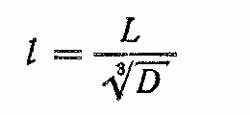
This parameter depends on the material and design of the hull, the weight of the engine, the saturation of the boat with equipment, fuel reserve, passenger capacity, etc. For cabin pleasure and tourist boats of normal design (made of wood), operated in displacement mode, the average values i=5-5.2. With a lightweight hull design with plywood skin or double diagonal i=5,6. If the relative length is less than 5, this indicates that the hull design is too heavy or the boat is overloaded with equipment. And the extra load will require additional costs of engine power and fuel, such a displacement boat will not be economical even at relatively low sailing speeds.
The distribution of displacement along the length of the boat has a great influence on the wave resistance. At the low speeds in question, the height of the waves formed at the hull of the vessel depends on the completeness of its extremities. The larger the underwater volume concentrated at the fore and aft stem, the higher the crests of transverse waves rise. Therefore, on displacement vessels, both the bow and stern extremities must be made relatively sharp, concentrating the main underwater volume near the midsection.
Graphically, the distribution of the underwater (submerged) volume along the length of the hull is represented as a drill line along the frames. The basis for this graph is the length along the waterline, and the ordinates laid up on each frame are the areas of the frames on a certain scale.
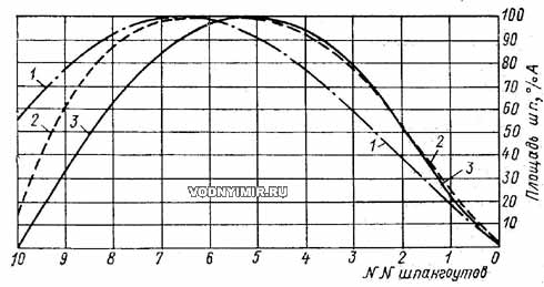
Typical drill lines on the frames.
1 — high—speed traveling boat; 2 — sea tourist boat of medium speed;
3 — seaworthy fishing boat with whaleboat stern
For low-speed boats and yachts, the typical drill curves along the frames in the bow and stern are concave; with increasing speed, when there is a tendency to trim aft, this curve usually becomes blunted in the aft part, and convex in the nose.
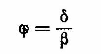
The area of the drill along the frames (taking into account the scale of length and areas) is equal to the displacement of the vessel; the position of its center of gravity coincides in length with the position of the center of the underwater volume — the center of magnitude, and the coefficient of completeness of the area bounded by the drill is equal to the prismatic coefficient of completeness of displacement:

Knowing this coefficient, it is possible to judge the distribution of displacement along the length of the hull, even without resorting to the construction of a drill: the higher the value of φ, the fuller the contours of the extremities of this hull.

Prismatic completeness coefficient.
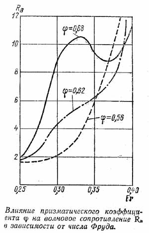
Tests of ship models in experimental pools have shown that the wave resistance strongly depends on the prismatic coefficient and, therefore, each relative velocity corresponds to an optimal value. The approximate figures for the considered speed range are as follows. For the Froude number 0.297 the value φ=0,53; 0,327 — 0,54; 0,357 — 0,58; 0,386 — 0,62; 0,426 — 0,64; 0,446 — 0,66; 0,475 — 0,68; 0,505 — 0,69.
The value of the coefficient φ is, as already noted, and directly dependent on the outline of the midsection frame — a more keeled outline corresponds to a larger value φ.
Let's mention another relationship — between the coefficients of total completeness, the prismatic coefficient and the coefficient of completeness of the midsection frame:
All these ratios must be taken into account when developing the contours of the future boat. That is why professional designers begin designing a new vessel with the most detailed acquaintance with all the data of similar prototype vessels, carefully analyze the experience of their operation. This avoids many mistakes.
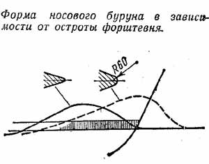
The main way to reduce the wave resistance when designing a displacement boat is to reduce the water pressure along with the flow meeting with the hull, i.e. at the stem. Here, the sharpening of the waterlines plays an important role-the angle of the hull's entrance into the water, measured between the tangent to the waterline and the diametrical plane. At the lowest speeds, when the wave resistance is small (Fr=0.20), this angle can be quite large — up to 25°. However, with an increase in the relative velocity to 0.25, it is necessary to reduce it to 18°, and at Fr more than 0.30 — even to 12-10°. However, it should not be forgotten that too elongated and «sunken» waterlines can cause a large rise in the bow breakers and «sticking» it to the skin; in a fresh wind and when pitching, splashes from it will be thrown onto the deck.
The shape of the cross section of the stem itself is also important. An increase in the height of the bow breakers and a noticeable movement of it forward inevitably causes a section close to a rectangle, or rounding along too large a radius. It is desirable that the stem should be pointed in the area of the running waterline — it should have a minimum radius of rounding.
The sharpness of the bow contours in the underwater part and at the KVL must be compensated by a sufficient collapse of the sides at the deck, as well as the use of splash guards on the sides that cut off the breakers from the sides; otherwise, in fresh weather, the ship will bury its nose into the wave, raise a lot of spray. It is also important to sufficiently tilt the stem forward: thanks to this, the moment damping the pitching pitching will increase smoothly, without slowing down the movement of the boat. In order to achieve the necessary bow sharpening of the waterlines, the largest frame in terms of area — the midsection frame — usually has to be shifted somewhat aft from the middle of the hull length.
 The role of the contours of the aft part of the hull is also great, which is primarily reduced to maintaining the correct trim at speeds corresponding to the separation of the second crest of the transverse wave from the stern. For the slowest vessels, a sharp feed of the type used on canoes, cruising or whaleboat feed is optimal, in which water flows around the hull along smooth trajectories and closes behind the stern without the formation of vortices. The hull with a sharp stern has approximately the same volumes of extremities and is ideal for swimming on a wave — it has stability on the course, it is easy to control. No wonder such contours are preferred for marine fishing vessels and lifeboats.
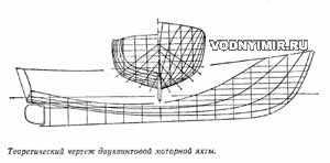 It is also possible to use a transom stern, but provided that the flat part of the transom begins above the KVL, and the running waterline is sufficiently pointed in the stern. This option will provide a good flow around the hull in combination with such advantages of the transom stern as a large deck area and the presence of a useful volume of the hull in the stern, an increase in the restoring moment with a large roll. The transom in this case should have a significant keel, and the buttocks rise steeply above the KVL.
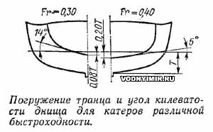
At higher speeds (Fr>0.30), the feed must have sufficient buoyancy to counteract the trim increasing with increasing speed. At Fr=0.30, a transom feed with a bottom keel of about 14° and a dip of the lower point of the transom by about 8% of the maximum draft of the hull is advisable. At Fr=0.40, the best results can be obtained with flatter contours of the stern — with a transom keel of about 6° and its immersion up to 20% of the boat's draft. The batox lines should become straighter and closer to the horizontal with increasing speed.
 On sea boats and fishing vessels, contours with a wide transom submerged in water are used extremely reluctantly: an imbalance between the volumes of the bow and stern is manifested in the excitement. The wave easily lifts the wide and full stern, and at the same time the narrow bow plunges deeply into the water. At the same time, the vessel sharply searches, going off with a passing wave, it can turn around with a lag to the wave; it is not easy to manage such a boat. When running against a wave, transom boats have an unpleasant pitching, they slap the stern hard against the water.
For river boats, the use of a transom stern is justified by an increase in stability due to a fuller waterline, although it is associated with an increase in the wetted surface.
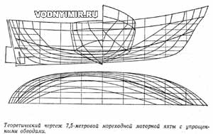 The greater the ratio of length L to width B along the waterline, the sharper the hull contours are obtained, the less its wave resistance. However, while increasing the CV, we must not forget another vital factor — transverse stability. The boat should not capsize under any extreme operating conditions — when sailing on a large wave, jerks when towing by another vessel, accidental movement of people to the side, etc. Therefore, most displacement boats with a length of 6-12 m are built with a length-to-width ratio within L/H=3.5-4.75; at the same time, the shorter the boat and the smaller its displacement, the relatively wider it should be to ensure the safety of navigation. Only in some cases (for example, in boats of the «dori» type, which have a large collapse of the sides in the surface part) L/V may exceed 5.
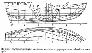
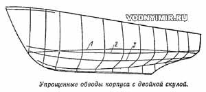 During the construction of displacement boats, round-cheeked hull contours became the most widespread. At the same time, positive experience has been accumulated in the operation of a large number of boats with simplified sharp-cheeked contours built with plywood or metal sheathing. All the general considerations discussed above apply to their design, but in addition, the designer must carefully work out the position of the sharp edges of the cheekbones. It is important that they cross the waterline at a relatively small angle to the horizontal both in the bow and in the stern; otherwise, significant turbulences form at the entrance of the cheekbones into the water, significantly increasing the water resistance to the movement of the vessel. You can lower the resistance almost to the level characteristic of round—cheeked boats by making a hull with several cheekbones - with faceted contours. In this case, part of the cheekbones are placed completely under water, and part is above water so that the cheekbones do not cross the running waterline.
If a hull is designed with simplified contours — with one cheekbone, then the cheekbone line should be raised to such a height above the KVL to obtain frames with the greatest possible keelness of the bottom and the angle of entry of the waterlines into the water equal to 12-20°. On the projection «side» of the theoretical drawing, the cheekbone line in the stern of the hulls designed for swimming with Fr=0.3 or less should come out of the water and rise up at the transom of the boat; at Fr=0.4, it should touch the waterline at the transom and sink into the water at high speeds. Only on planing boats, the cheekbone line should be horizontal all the way from the midsection to the transom.
In the section «Motorboats, boats, yachts — miscellaneous, reviews, tips»
Share this page in the social. networks or bookmark:
