Cabin boat from the motorboat. Conversion of the «Progress» motorboat into a mini-cruiser
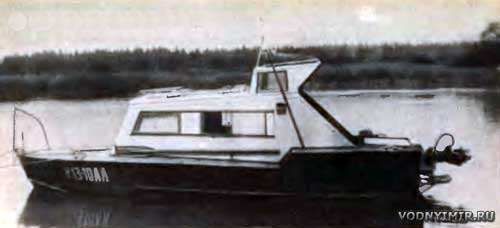
The industry is rather slow, if not more sharply, reacting to the constantly changing market situation associated with water recreation. Many years ago, new higher prices for gasoline and lubricating oils were introduced, which made swimming (and even walking!) practically inaccessible for us pensioners. on the previously popular «Progresses» planing under two 30-strong «Vortices».
We have nowhere to hurry. Let the boat travel more kilometers on the same amount of gasoline — after all, the weight of the cans is also of considerable importance for an elderly person.
For some time, operations with a 48-kilogram «Whirlwind» have also become difficult for me — carrying it from the storage place to the boat, hanging it on the transom, removing it from the boat, etc. There was a dream of a leisurely displacement cabin boat with an economical stationary engine, with a cabin that would protect from rain and wind. This is how the boat presented in the photo and sketch appeared, equipped with a four-stroke carburetor engine «UD-25» with air cooling. Perhaps this is the most currently available low-power engine that can be used on a boat.
General layout of the boat
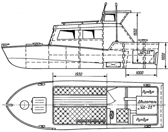
The hull of the boat was lengthened by 1100 mm, and I purchased the main materials for this in the Young Technician store. In the spring of 1982 I carefully removed the rivets that secured the transom to the skin and removed it. The details of the longitudinal set were increased from the stern side to the appropriate length, two additional frames from a 40x40x3 square were installed. The transom also had to be slightly reconstructed — to increase its height and reduce its width, to install a new engine board along the entire width. It is to it that the rotary corner column is attached, which is used to transmit rotation. The engine was mounted on wooden bars laid through rubber gaskets on frames 6 and 7 and fastened to the transom board.
The frame of the cabin is assembled from duralumin squares 20x20x2 and sheathed with sheets 1.2 mm thick. All the joints of the hull structures were sealed during riveting with a sealer strip impregnated with sealant. The bulkhead separating the cabin from the cockpit is made waterproof to a height of 300 mm from the bottom. The second watertight bulkhead with a height of 350 mm is on the frame 6. Thus, the engine compartment is reliably isolated from the cockpit and cabin.
The cabin is equipped with two sofas, under which bulky lockers for equipment have turned out. The walls of the cabin and the sides in the cabin are covered with styrofoam with a thickness of 20 mm and decorative fabric on top of it. I protected the helmsman's place in the cockpit from rain and wind with a half-cabin open from the stern. Here , under the payoles, there is a stationary gas tank with a capacity of 30 liters . Lockers for spare parts and tools are equipped on the sides of the engine.
The engine «UD-25» is a two-cylinder, developing a power of 10 hp at 3000 rpm. Its weight is only 52 kg, and the specific fuel consumption is 320 g/hp-h. When it is installed on the boat, a flywheel from the «Vortex» motor was installed on the side of the output shaft, which serves as a pulley for transmitting rotation to a DC generator and simultaneously reduces engine vibration. A small coil is mounted in the engine crankcase to cool the oil with seawater (it is supplied due to the high-speed pressure of the water flow thrown by the propeller blades). After cooling the engine cylinders, the warm air is discharged through a special air duct outside the boat. The exhaust pipe of the exhaust gases is withdrawn into the transom. To reduce vibration and structural noise, the motor is mounted on rubber shock absorbers and connected to the transmission shaft at propeller through elastic coupling.
Speaker device
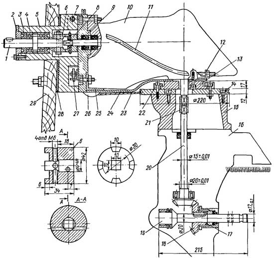
1 — drive shaft; 2 — cover; 3 — cuff; 4 — ball bearing No. 204; 5 — bearing housing; 6 — drive coupling; 7 — column suspension axle; 8 — driven coupling; 9 — folding plate; 10 — upper gearbox; 11 — thrust (2 pcs.); 12 — square; 13 — spacer Ø120x17; 14 — column rotation disc; 15 — deadwood; 16 — lower gearbox; 17 — washer; 18 — driven gear of the lower gearbox m=2.5, z=22; 19 — propeller shaft; 20 — shaft-gear m=2,5, z=20; 21 — coupling; 22 — ring; 23 — sturtros; 24 — bracket 5x120; 25 — square 40x40x4; 26 — sturtros block; 27 — reverse control drive; 28 — gasket; 29 — transom.
Folding plate (a) and bearing housing (b)
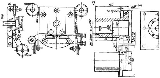
A homemade angular column made of two gearboxes of outboard motors «Whirlwind» is used as a transmission. The folding part is attached to the bearing housing 5 on the axis 7, and the bearing housing to the transom — using 8 bolts M8 through a rubber gasket 28. The upper gearbox 10 is connected to the folding plate 9 by three bolts passing through the available holes. An additional support for the folding part is the bracket 24, which is also attached to the plate 9.
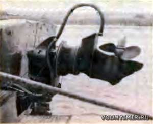 Corner folding column. |
The upper gearbox was used almost unchanged, but in the lower gearbox some parts had to be replaced or modified. At the end of the former propeller shaft, a 10x10 mm tetrahedron is made to connect to the output shaft of the upper gearbox. To lower the speed of the propeller shaft, it was necessary to re-manufacture the gear shaft 20, the lower gear 18 and the propeller shaft 19. The remaining parts (thrust bearing, needle bearing and glass assembly) are left as standard.
The rotary part of the column is attached to its upper part through a spacer 13, which is connected by eight screws to the upper gearbox and eight M6 screws to the bracket. A ring 22 is put on the spacer, which rotates together with a disk 14 connected to the sturtros 23. The deadwood 15 is also attached to the disc 14. It can have any height depending on the distance between the engine crankshaft and the propeller shaft. With a significant axial distance, it will be necessary to apply a torsion vertical roller, as on an outboard motor. I managed to limit myself to the coupling 21. The lower gearbox is attached to the deadwood by means of three screws through the standard holes, as on an outboard motor.
The connection of the drive shafts of the engine and the angular column is carried out by means of a cam coupling. When the column is reclined, for example, in the case of a collision with a floating log or a stone, the clutch is disconnected and the engine runs idle. Reversing is provided by switching the standard device in the upper gearbox of the column; the reverse gear and other parts of the device for reversing and idling are removed from the lower gear.
I usually use two propellers on my boat. One of them is a three-bladed 240 mm diameter with variable pitch and the second is 280 mm diameter with a fixed pitch of 240 mm. A boat with a full load on calm water goes at a speed of 10.5-11 km/h. I measured fuel consumption in a 500-kilometer hike from Leningrad to Sviri and back. On average, it turned out to be 27-28 liters per 100 km of the traveled path. During the entire navigation of 1988, only 7 liters of oil were consumed. The corner column has fully met all my expectations.
Boat projects for self-construction
Share this page in the social. networks or bookmark:
