Collapsible boat with soft skin
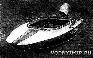 The complexity of solving the problem of urban parking, winter storage of ships, as well as their transportation by land, forces many water-motor tourists to be interested in collapsible structures. Here are the drawings of a small boat for a motor with a capacity of up to 10 hp., as if combining the advantages of a collapsible kayak in terms of ease of storage and transportation and «real» motor boats for 2-4 people.
This mini-boat with a soft skin in disassembled form is packed in three places, which are reliably accepted for transportation in a taxi with three passengers. Three bales have approximately the same weight — 20 kg each; frames and cans are placed in one of them, a longitudinal set in the other, and a skin in the third. It is clear that, if desired, you can «decompose» them in any other combination into any number of packaging places.
| Basic data of the collapsible boat | |
|---|---|
| Longest length, m | 3,0 |
| Width, m | 1,35 |
| Side height amidships, m | 0,4 |
| Body weight, kg | 60 |
| Speed from 1 person. on board under the engine «Moscow», km/h | over 30 |
The issue of purchasing the necessary materials and parts is solved relatively simply. In addition to pine slats and boards, it took: a sheet of plywood 3 mm thick (for payoles), a piece of 4 mm 400x1300 (for transom) and 10 mm trimming (200x300, 160x400, 50x750 - 4 pcs.); 110 loops; 1.5-2 mm thick duralumin trimming; 0.6 kg of 2.5 (3.0) duralumin rivets)x22 and a little bit of screws 3x15 and 3,5x20.
I advise you to start the construction with the manufacture of a curved part of the keel, glued out of two 10x50 rails on a special template with a size of 200x1600, cut from a board with a thickness of 50 mm. The ends of the rails are steamed, passed into the lumen of the bracket mounted on the nose end of the template, and pressed with wedges. With the help of a strong rope, the slats are pulled up to the template until they fit snugly along the entire length and are left to dry. Having smeared with glue, they are pressed a second time, while pushing a little beyond the mark of shp. 1, which makes it possible to adjust the lifting height when assembling the housing. When gluing the slats of the stern half of the keel, pressing is done with small nails. When cutting parts, it is better to make sure that the joints of neighboring stringers do not lie in the same plane, but are «dispersed» by 150-200 mm.
The production of non-collapsible (one-piece) frame frames also begins with the gluing of bent parts — beams on the shp. 1, 2, 5, the upper edge of the transom and the aft bulwark (on the shp. 5). The size of the loss for each frame is set by a plaz table, where the heights at the side and in the DP are indicated. You can make a template for the transom, where the largest arrow is 60 mm, and then adjust it, taking turns adjusting the plaza for the rest of the frames. Beams are glued out of four 10x15 rails (it is better to strengthen the beams on shp. 2 a little by making it out of five or six such rails).
Construction of a collapsible boat with a soft skin
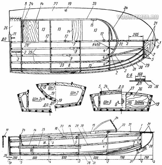
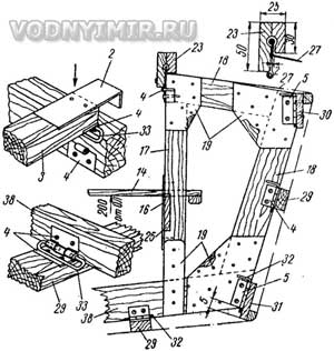
1 — overhead strip (stainless steel steel or D16) 3x30x600 with a mooring ring hole on the end protruding through a slot in the skin; attached to children 3, 6 and 20 with three screws with wing nuts; 2 — a bar at the ends of deck stringers; duralumin 1,5x30x75; 9 pcs.; 3 — deck stringer (carlengs) 15x30; 2 220 pcs. and 3 pcs. 700 pcs.; 4 — a window loop with a length of 30 mm; 60 pcs.; 5 — a window loop with a length of 40 mm; 50 pcs.; 6 — a hinged flap; plywood 10x250x750; 7, 8, 9 — fittings for connecting the bow and stern parts of the longitudinal set; 10 — a poduklyuchina, 2 pcs.; 11 — engine trim on the transom outside; plywood 10x200x300 on a duralumin suspension made of plates 1.5x70x200; 12 — turntables — fixers of payoles; 13 — payoles; 7 boards made of plywood δ=3; 14 — seats, 12 mm board; aft has a backrest made of 6 mm plywood, fixed on hinges; 15 — bulwark lock, 2 pcs.; duralumin plate box 1,5x50x100; 16 — latches for the position of the support rails 25, duralumin 2x15x100; 6 pcs.; 17 — rack, 15x40; 18 — beams and side branches (toptimbers) of frame frames, 15x40; 19 — duralumin knits-lining 1.5 mm thick on both sides; between the knits — crackers δ=15; 20 — stem, 2x50 duralumin strip; fasten to the keel and to the breech with 6 bolts 21; 21 — 3x30 bolt with a lamb nut; 5 pcs.; 22, 23, 24 — bulwark parts; 25 — podbanochaya rail (podlegars), 10x50x1300; 26 — the aft part of the deck; 27 — deck; 28 — keel, 20x50; 29 — bottom and side stringers, 15x30; 30 — anchor beam, 10x50 and 10x15 along the edge; 31 — zygomatic stringer, 10x50 and 10x15 along the edge; 32 — L-shaped nagel; 33 — clasp (option instead of an L-shaped nagel); 34 — windscreen frame; bent plywood or duralumin; 35 — engine rack, 15x60; 2 pcs.; 36 — transom lining, plywood δ=4; 37 — transom reinforcement, plywood 10x160x400; 38 — bottom part of the frame frame (flor); on shp.1, 2 and 3 — 15x40 with a joint in DP on duralumin linings; on shp. 4, 5 and transom — 15x50 solid.
Outline of the hull
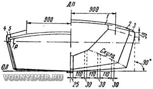
To assemble the frames, it is necessary to split the plaz on a plywood sheet of at least 600x1400 and 8-10 mm thick — draw the outlines of all six frames according to the plaz table. Having adjusted the parts cut from pine rails with a thickness of 15 mm along the plaza, the joints are lubricated with glue and the parts are placed on the plaza again, assembling a closed frame from them. Naturally, previously manufactured beams and racks (on shp. 3, 4, 5), and corner fillers (crackers) are put in place. All installed parts are attached to the plaza with nails. To prevent sticking to plywood, strips of paper are placed under the joints. After the glue dries, the nails are removed, and the finished frame frame is removed from the plaza. It remains in the places where plywood knits are laid to trim the planes with a plane and fix the knits lubricated with glue with nails, without damaging the gluing. So all the frames are assembled in turn. The transom is cut along the plaza into a clean size from waterproof plywood, after which the details of the strapping and reinforcement are placed under the motor.
Table of plaz ordinates
| shp-ta no. | Tr | 5 | 4 | 3 | 2 | 1 | 0 |
| Heights from OL, mm | |||||||
| Deck in DP | 380 | 385 | 420 | 459 | 525 | 506 | 503 |
| Board | 320 | 335 | 370 | 404 | 440 | 484 | 500 |
| Cheekbone | 8 | 10 | 15 | 40 | 96 | 220 | — |
| Keel top | — | — | — | — | 20 | 160 | — |
| Half-width from DP, mm | |||||||
| Board | 630 | 635 | 650 | 646 | 590 | 375 | — |
| Cheekbone | 550 | 560 | 585 | 570 | 480 | 175 | — |
| Notes: The outlines of the outer edges of the frame frames are set. | |||||||
The next stage of work is the installation of fittings, i.e. connecting parts, thanks to which the keel, the anchor beam and the stringer are assembled (each of two parts), and then fastened to the frames, forming a rigid frame on which the skin is stretched. A fairly simple and reliable connection system has been used, proven by many years of operation of kayaks with a wooden set.
Nodes connecting parts of the longitudinal set
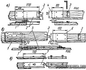
a — keel; b — privalny beam, side and zygomatic stringers; c — bottom stringers.
1 — gasket (plywood or plastic) according to the thickness of the tongue 4; 2 — lock box; billet 170x80; 3 — half-loop; 4 — tongue; 6 — lining, pine 12x50x280; for a privalny bar, the lining should be 500 mm long (poduklyuchiny are attached to it); 6 — tongue; billet 100x70; 7 — lock box; blank 50x150.
To connect the longitudinal set with the transverse one, the most common window hinges (attachments) are used. The hinges must be disassembled by knocking out the nail after filing the rivet, and install exactly according to the marking one part on the stringer, and the other on the frame. The hinges are fastened with duralumin rivets. The loop on the frame should not protrude beyond its lower edge, so that when assembling the set, the frame fits tightly onto the plane of the bottom stringer. Nagels from 40-millimeter loops installed at the joints with the keel, the anchor beam and the zygomatic stringer will fit to 30-millimeter. To do this, 10 mm is bent in the vise (so that the nail does not fall out), and at right angles one end is slightly sawn off to the other under the cone. For the remaining loops, the nagels are cut from steel wire. For horizontal loops, they can be bent in the form of a «fastener» shown in the sketch. Such fasteners cannot be lost; assembly and disassembly of the case will take less time.
All fittings for connecting the parts of the longitudinal set to each other are made from duralumin scraps and are also placed on rivets.
The marking of the places where the hinges are installed on the privalny beam, zygomatic and side stringers is made locally. In other words, you need to assemble the keel and bottom stringers, install the transom and all the frames on them, and then bend the rails of the side set along the frames, pulling and securing them with a cord or strong twine. Having put the set on both sides, carefully check the correct position of the frames and transom and mark the position of the hinges on the rails.
After removing the slats, check the coincidence of the marks on the right and left sides; only after achieving complete symmetry, you can rivet the loops.
Note that the slats for the on-board kit should be selected in pairs with the same elasticity, especially in the bow of the hull. To increase the rigidity and fix the bend in the nose, glue the 10x15 slats with clamps and nails along the upper edge of the privalny beam and along the lower edge of the zygomatic stringer. The first bottom stringers from the keel bend to the shp. 1 with difficulty, so I advise you to saw them along with a thin hacksaw at a length of 600 mm, and then glue the saw with nails pressed. The second and third stringers from the keel in the nose are attached by loops to the zygomatic stringer with a fitting in place. Deck rails — carlengs — are adjusted last.
It is best to cut the folding bow brashtuk in place — on the finished body; then the plywood is soaked in hot water and bent along the arc of the beam shp. 1, and after drying, the brashtuk and beams are connected by three non-removable 40-millimeter loops. The stem, bent out of the duralumin strip (to increase the rigidity of the bow, you can make the stem in the form of a solid vertical part, sawn out of thick plywood or board and fixed to the shp. 1 on hinges.), is also manufactured locally. Thus, you set the shape of the bow of the boat yourself, achieving a smooth completion of the keel lines (side view) and the rest bars (in plan). The upper part of the stem bends horizontally to a length of about 200 m and is wound under the breech. Then a metal strip 1 (with a mooring ring — hole at the bow end) is superimposed on top of the breech and the nose of the carlengs in the DP and holes are drilled in place to fasten the parts together with two 3x30 bolts with wing nuts 21. The lower part of the stem is simply superimposed on the bow end of the keel and, when assembling the hull, is fastened with two of the same bolts.
The bulwark at the edges of the cockpit consists of four parts — the bow 22, curved along the radius, two side 23 and one aft 24 walls. Parts 22 and 23 are glued together (with screws pressed in) each of the two rails in which a semicircular groove with a radius of 4 mm is selected. The edge of a soft «deck» (deck) is inserted into the resulting cylindrical hole, into which a rubber cord with a diameter of 6 mm is sewn on glue. Do not forget to remove 2-3 millimeters in thickness in a 30-millimeter-high rail to pass the edge of the soundboard! The slats of the nasal wall will have to be steamed first, so that it is easier to bend them along a radius of 450 mm. It is possible to glue children to simplify bending. 22 of plywood strips, leaving a groove of rectangular section 8x8.
The finished frame is painted with hot drying oil and kept fully assembled for several days to allow the shape of bent longitudinal ties to be fixed.
The payoles in the cockpit are cut out in place and placed on the bottom set. On the lower side, two guide plates of 2x30x70 duralumin are riveted to the payoles, which go under the frames; cutouts are made for the loops, which can simultaneously serve as latches that lock the L-shaped nagels from falling out. Plates and cutouts do not allow the payoles to move to the side. In addition, the shields are fixed with turntables on the keel. The can seats are placed with the edges on the 10x50 longitudinal slats inserted into the slots on the frame racks.
The shell is glued together from four strips of rubberized fabric with a thickness of about 2 mm (fabric consumption is about 8 nor. m); two, connected along the keel, form a bottom panel, which also covers the transom, and the two sides are glued together with the bottom on the zygomatic stringer. The glued shell is stitched along the gluing lines, then all seams on both sides are pasted with strips of the same rubberized fabric, the shell is stretched over the frame, bending a margin of 80 mm on the rest bars, and temporarily fastened. A seam marking is made along the upper outer face of the privalny beam to connect the shell with the deck.
The deck is sewn from a light tarpaulin (material consumption is 7 sq. m). For its initial cutting, it is necessary to lay the fully assembled bulwark on the material leveled on the floor, and outline the cockpit contour from the inside along the perimeter of the bulwark, continuing it to the transom. Stepping back from this contour line by 50 mm inside the cockpit, excess material can be cut off. Now it is necessary to glue a rubber cord along the contour line, smoothly and tightly fitting it with the edge of the soundboard; the covered cord is stitched, forming a flexible roller along the edge.
It remains to sew the soundboard to the shell. To do this, putting the details of the bulwark on the inner edge of the deck with a rubber roller, install the bulwark on the frame and fasten the hinges (fasteners) on the hinges. The deck is leveled along the bulwark and stretched on the sides and into the nose, after which the seam is marked; transverse marks that coincide with the marks on the shell and frame will serve to protect against misalignment during stitching.
The aft part of deck 26 is cut out separately and sewn to the shell along the upper edge of the transom. The inner edge of the children. 26 is passed under the aft wall of the bulwark and stretched, putting it on with grommets on round screw heads in children. 24 and (at the nasal corners) on the beam shp. 5. In the places of the loops connecting the children. 24 with beams shp. 5, you will have to make slots in the deck. In addition, it is necessary to make two slots at the transom for the passage of the legs of the outboard motor clamp. To the aft part of the children. 27 two valves are sewn on, closing the ends of the longitudinal rollers, with grommets for connecting the cord with children. 26.
Welded Poduklyuchiny: tubes-bushings with an inner hole d=12 mm are welded to a 3x50x100 steel plate.
Two frames for fixing the windshield (plexiglass) are cut out of plywood and bent after steaming; between each other (according to DP) and with children. 22 bulwarks, they are connected on hinges.
The awning is placed on arcs of duralumin tubes. Clamps are screwed to secure the arches and bulwarks. The awning is attached to the windscreen frame and to the bulwark by grommets worn on the screw heads. In the stern, the awning is stretched by the raised motor and closes it.
Boat projects for self-construction
Share this page in the social. networks or bookmark:
