Amphibious boat with your own hands. Homemade hovercraft
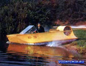 One winter, when I was walking along the bank of the Daugava, looking at the snow-covered boats, I had an idea — to create an all-season vehicle, i.e. amphibious, which could be used in winter.
After much thought, my choice fell on a two-seat hovercraft. At first, I had nothing but a huge desire to create such a structure. The technical literature available to me summarized the experience of creating only large SVPs, and I could not find any data on small devices for recreational and sports purposes, especially since our industry does not produce such SVPs. So, it was possible to rely only on one's own strength and experience (my amphibious boat based on the Yantar motorboat was reported in the «Boats and yachts» at the time; see No. 61).
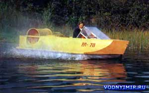 Anticipating that in the future I might have followers, and with positive results, the industry might also be interested in my device, I decided to design it on the basis of well-mastered and commercially available two-stroke engines.
In principle, the hovercraft experiences significantly lower loads than the traditional planing hull of the boat; this allows its design to be made lighter. At the same time, there is an additional requirement: the body of the device must have a low aerodynamic drag. This should be taken into account when developing a theoretical drawing.
| Basic data of an amphibious hovercraft | |
|---|---|
| Length, m | 3,70 |
| Width, m | 1,80 |
| Side height, m | 0,60 |
| Air cushion height, m | 0,30 |
| Lifting power, hp | 12 |
| Traction plant power, hp | 25 |
| Payload, kg | 150 |
| Total weight, kg | 120 |
| Speed, km/h | 60 |
| Fuel consumption, l/h | 15 |
| Fuel tank capacity, l | 30 |
Schematic diagram of an amphibious hovercraft
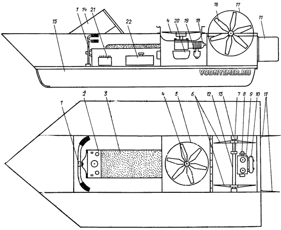
1 — steering wheel; 2 — instrument panel; 3 — longitudinal seat; 4 — lifting fan; 5 — fan casing; 6 — traction fans; 7 — fan shaft pulley; 8 — engine pulley; 9 — traction motor; 10 — muffler; 11 — sashes 12 — fan shaft; 13 — fan shaft bearings; 14 — windscreen; 15 — flexible fence; 16 — traction fan; 17 — traction fan casing; 18 — lifting engine; 19 — lifting engine muffler; 20 — electric starter; 21 — battery; 22 — fuel tank.
I made a set of housing from spruce slats with a 50x30 cross section and sheathed with 4 mm plywood on epoxy glue. I did not do fiberglass pasting, fearing an increase in the weight of the device. To ensure unsinkability, I put two waterproof bulkheads in each of the onboard compartments, and also filled the compartments with foam.
A two-engine powerplant scheme is selected, i.e. one of the engines works to lift the device, creating an excess pressure (air cushion) under its bottom, and the second provides movement — creates horizontal thrust. The lifting engine, based on the calculation, should have a power of 10-15 hp. According to the main data, the engine from the Tula-200 scooter turned out to be the most suitable, but since neither the fasteners nor the bearings satisfied it for constructive reasons, a new crankcase had to be cast from aluminum alloy. This motor drives a 6-blade fan with a diameter of 600 mm. The total weight of the lifting power plant, together with the fasteners and the electric starter, turned out to be about 30 kg.
One of the most difficult stages turned out to be the production of a skirt — a flexible cushion fence that quickly wears out during operation. Commercially available canvas fabric with a width of 0.75 m was used. Due to the complex configuration of the joints, about 14 m of such fabric was required. The strip was cut into pieces with a length equal to the length of the side, with an allowance for a rather complex shape of the joints. After giving the necessary shape, the joints were sewn together. The edges of the fabric were attached to the body of the device with 2x20 duralumin strips. To increase the wear resistance, I impregnated the installed flexible fence with rubber glue, to which I added aluminum powder, which gives an elegant look. This technology makes it possible to restore the flexible fence in case of an accident and as it wears out, similar to the build-up of the tread of a car tire. It should be emphasized that the manufacture of flexible fencing does not just take a lot of time, but requires special care and patience.
The assembly of the hull and the installation of a flexible fence were carried out in the up position with the keel. Then the hull was unrolled and a lifting power plant was installed in the 800x800 shaft. The installation control system was summed up, and now the most crucial moment has come; its testing. Will the calculations be justified, will a relatively low-power engine lift such a device?
Already at an average engine speed, the amphibian rose with me and hovered at a height of about 30 cm from the ground. The reserve of lifting force turned out to be quite enough for a warmed-up engine at full speed to lift even four. In the very first minutes of these tests, the features of the device began to be revealed. After the appropriate alignment, he moved freely on an air cushion in any direction, even from a small effort applied. It seemed as if he was floating on a water surface.
The success of the first test of the lifting rig and the hull as a whole inspired me. Having secured the windshield, I proceeded to install the traction power plant. At first, it seemed advisable to take advantage of the extensive experience in the construction and operation of aerial sleds and install an engine with a relatively large diameter propeller on the aft deck. However, it should be taken into account that with such a «classic» version, the center of gravity of such a small device would significantly increase, which would inevitably affect its driving performance and, most importantly, safety. Therefore, I decided to use two traction engines, completely similar to the lifting one, and installed them in the aft part of the amphibian, but not on the deck, but on the sides. After I manufactured and mounted a motorcycle-type control drive and installed relatively small diameter traction propellers («fans»), the first version of the hovercraft was ready for sea trials.
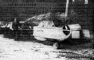 A special trailer was made to transport the amphibian behind the Zhiguli car. |
A special trailer was made to transport the amphibian behind the Zhiguli car, and in the summer of 1978 I loaded my apparatus onto it and delivered it to a meadow near a lake near Riga. An exciting moment has come. Surrounded by friends and curious people, I took the driver's seat, started the lifting engine, and my new boat hung over the meadow. Started both traction engines. With an increase in the number of their revolutions, the amphibian began to move across the meadow. And then it became clear that many years of experience driving a car and a motorboat is clearly not enough. All the old skills are no good. It is necessary to master the methods of controlling a hovercraft, which can spin endlessly in one place, like a yule. With increasing speed, the turning radius also increased. Any surface irregularities caused the device to rotate.
Having mastered the controls, I sent the amphibian along the gentle shore to the surface of the lake. Once above the water, the device immediately began to lose speed. The traction engines began to stall alternately, flooded with spray escaping from under the flexible air cushion fence. When passing overgrown areas of the lake, the fans drew in reeds, the edges of their blades were painted. When I turned off the engines, and then decided to try to start from the water, nothing happened: my device could not escape from the «pit» formed by the pillow.
In general, it was a failure. However, the first defeat did not stop me. I came to the conclusion that with the existing characteristics for my hovercraft, the power of the traction unit is insufficient; that is why it could not move forward when starting from the surface of the lake.
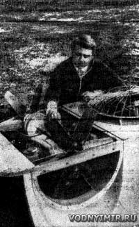 For the winter of 1979 I completely he redesigned the amphibian, reducing the length of its hull to 3.70 m, and the width to 1.80 m. He also designed a completely new traction unit, completely protected from splashes and from contact with grass and reeds. To simplify the control of the installation and reduce its weight, one traction motor was used instead of two. The power head of the 25-horsepower outboard motor «Whirlwind-M» with a completely redesigned cooling system was used. The closed cooling system with a volume of 1.5 liters is filled with antifreeze. The torque of the engine is transmitted to the «propeller» shaft of the fans located across the apparatus by means of two V-belts. Six-blade fans pump air into the chamber, from which it escapes (simultaneously cooling the engine) aft through a square nozzle equipped with control flaps. From an aerodynamic point of view, such a traction system is probably not very perfect, but it is quite reliable, compact and creates a thrust of about 30 kgf, which turned out to be quite sufficient.
In the middle of the summer of 1979, my device was again transported to the same meadow. Having mastered the controls, I directed him to the lake. This time, once above the water, he continued to move without losing speed, as if on the surface of ice. Easily, without hindrance, I overcame shallows and reeds; it was especially pleasant to move over overgrown areas of the lake, there was not even a foggy trace left. On a straight section, one of the owners «Kazanki» with the motor «Whirlwind-M» went on a parallel course, but soon fell behind.
The described device caused particular surprise among ice fishing enthusiasts when I continued testing the amphibian in winter on ice that was covered with a layer of snow about 30 cm thick. There was a real expanse on the ice! The speed could be increased to the maximum. I didn't measure it exactly, but the experience of the car driver suggests that it was approaching 100 km/h. At the same time, the amphibian freely overcame deep traces from the motor-carts.
A small film was shot and shown by the Riga TV studio, after which I began to receive many requests from those wishing to build such an amphibious vehicle.
Boat projects for self-construction
Share this page in the social. networks or bookmark:
