
A boat on one hydrofoil
The effect of hydrofoils is well known: the lifting force arising on them completely pushes the hull of the boat out of the water, which dramatically increases the speed of travel without increasing the power consumed by the engines.
Currently, the most common option is to install the stern and bow wings with approximately equal distribution of the weight of the boat between them (while both the bow and stern wings may consist of one or two wings located on the sides). The two-wing scheme provides the highest hydrodynamic quality at the estimated maximum speed, however, its implementation is usually associated with great difficulties in the development of a propeller-driven complex and fine-tuning of built boats. In search of simplification, the designers came to the paradoxical idea of abandoning the aft wing.
 It turned out that a sufficient effect can be obtained with a single-wing scheme. One hydrofoil is installed in the bow of the boat, which takes about half the weight of the boat. On the move, when the lifting force on the wing reaches a certain value, the bow tip of the boat rises above the water and the boat moves only on the wing and on a small section of the bottom near the transom.
Since the quality of the planing plate, a type of which is the aft part of the bottom of the boat, does not exceed K=10, it is obvious that theoretically in most cases a boat on one hydrofoil will lose diptera in speed. However, we can also talk about certain advantages of the simplified single-wing scheme, which allow boats with a single bow hydrofoil practically compete with diptera.
First, the design of the wing device as a whole is simplified; the costs of its manufacture are halved, it turns out to be much lighter; if necessary, one nose wing is much easier to perform retractable, rotary or with an automatically controlled angle of attack than devices with two wings.
Secondly, the design of the aft propulsion and steering complex (bracket, propeller, rudder) is simplified; the angle of inclination of the propeller shaft axis is reduced and the working conditions of the propeller are improved regardless of the location of the engine; the overall draft of the boat by the stern is reduced. When overcoming the «hump» of resistance and reaching the wing, the engine experiences less overload.
The seaworthiness of a boat on one hydrofoil even increases due to a decrease in the swing of the bow and improved conditions for working together on the excitement of the wing and the hull of the boat. (This refers to the «dips» of the bow wing, which, if there is a wing in the stern, lead to the appearance of negative angles of attack and corresponding forces that cause the nose wing to sink, which is accompanied by an increase in resistance and a decrease in speed.)
It is also very important that during the sea trials of a boat with one bow hydrofoil, it is easier to choose the optimal values of the angles of its installation, the height of the racks and other elements. At the same time, the fine-tuning of the propeller is significantly facilitated, which is carried out simultaneously with the fine-tuning of the wing in order to obtain full coordination of the propulsion and mechanical installation, which allows to develop the highest possible speed.
We should also add such a plus as the ability to equip an already designed and built planing boat with a bow wing without any change in the line of the propeller shaft and alteration of the protruding parts. (In some cases, such a solution allows you to get the optimal running trim of an unsuccessfully designed boat — with bow alignment, with a bulge of the bottom, etc.)
In the foreign press, reports about the construction of single-wing boats appeared repeatedly. As an example of installing a bow wing on an existing serial vessel, one can name a successful experiment with a traveling boat «Chaika», built in 1961 (see V. I. Blyumin, L. A. Ivanov and M. B. Maseev, «Hydrofoil transport vessels», pp. 38-40). The main data of the boat: length — 6.1 m; width — 1.86 m; displacement — 1.60 t; engine power — 90 hp. The maximum speed (48 km/h) thanks to the nose wing increased by 8 km/h while improving seaworthiness. The authors recommend using bow hydrofoils on all other operated boats of the «Chaika» type.
One wing was also installed (Fig. 1) on a 6-seat service and traveling boat of type 370M, having a length of 6.18 m; width — 2.03 m; total displacement — 1.95 tons; engine power — 77 hp. The speed increased from 40 to 48-50 km / h.
Fig. 1. Service and traveling boat 370M with a bow hydrofoil

Finally, it can be noted that back in the 60s there were several reports of attempts to apply a single-wing scheme on serial motor boats to increase the speed of travel with the limited power of outboard motors available at that time.
If we talk about the theoretical justification of the scheme under consideration, it is worth mentioning, for example, that the installation of one bow wing is recommended by M. M. Korotkov in the article «Features of the use of hydrofoils on small vessels» («Shipbuilding» No. 11, 1968); the expected increase in speed, according to his estimate, is from 10 up to 20%.
The resistivity curves shown in Fig. 2 R/Δ of wingless boats and boats with one bow wing show that the installation of the wing is justified only with FrΔ>3. (Let's make a reservation right away that all the recommendations of this article relate to planing boats with traditional sharp-cheeked contours; with L/B=3-6 and bottom keeling angles on the transom 3-6° and midsection about 15°.)
Fig. 2. Typical resistivity curves R /Δ = f (FrΔ)

1 — an ordinary sharp-cheeked boat; 2 — a sharp-cheeked boat with a transverse redan; 3 — a sharp-cheeked boat with a bow hydrofoil.
The design of the nose wing and its hydrodynamic calculation for the single-wing and double-wing versions of the boat are almost the same, except for a certain reduction in the height of the single-wing struts in order to reduce the running trim.
It is advisable to install a bow hydrofoil if the expected stroke speed is at least
![]()
where Δ is the displacement of the boat, m³.
At lower speeds, the bow hydrofoil does not bring significant benefits, since its area must be excessively large to create the necessary lifting force; it can even cause an increase in the resistance of the boat and a drop in speed compared to the wingless version.
At the initial design stage, the value of the highest speed of a bow-wing boat with a known displacement Δ and engine power Ne is defined as
![]()
where η is the propulsive coefficient, To=Δ/R is the hydrodynamic quality, which is the ratio of Δ to full resistance R when running on the nose wing.
The approximate value of To can be removed from the curve shown in Fig. 3, showing a decrease in to of a winged boat with an increase in its speed. (This happens because with respect to Δ/R the lifting force of the wing and the planing bottom is equal in magnitude to the boat, with an increase in V should not change, because otherwise the movement will be unstable, and the resistance R in the denominator gradually increases.)
Fig. 3. Approximate dependences of hydrodynamic quality K and propulsive quality K on the Froude number

1 — single-winged boat; 2 — ordinary sharp-cheeked boat; 3 — sharp-cheeked boat with a transverse redan; 4 — double-winged boat.
The propulsive coefficient characterizing the efficiency of using engine power can be taken within η=0,50-0,60.
It is advisable to immediately determine the value of the product Toη, which is a coefficient of propulsive quality:
![]()
The dotted line in Fig. 3 characterizes the simultaneous increase of V and to planing boats when installing hydrofoils. Moving parallel to this line from one curve to another, one can roughly estimate the speed increase due to the presence of a transverse redan or hydrofoil.
Having made sure of the expediency of installing a bow hydrofoil, it is necessary to determine its area and location. To this end, it is necessary to set the part of the weight of the boat that the wing should carry. Most often it is taken equal to 50-60% of the total weight of the boat. Thus, the lift on the wing should be
![]()
The installation location of the wing is from the expression
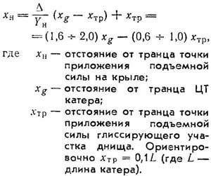
We should strive to ensure that the wing is located in a relatively wide and convenient place for fixing the hull of the boat. When designing a new vessel, it may even be advisable to widen the hull.
Wing bearing area
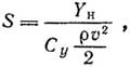
where Су is the wing lift coefficient.
The value of Су should be chosen taking into account many circumstances, the most important of which are ensuring high hydrodynamic quality and the absence of cavitation of the wing at the design speed. For speeds of 25-40 knots, these conditions are satisfied by a value close to Су=0.15-0.20.
Lifting force on the hydrofoil must be constant in all driving modes. Therefore, it is necessary to provide some additional elements - bearing wing areas that would work in intermediate modes (for example, in the wing exit mode), when the speed is even lower than the calculated one, and therefore the lifting force arising on the main wing is insufficient, and would leave the water at full speed. For this purpose, various kinds of combined schemes are used, including, in addition to the main carrier plane always in the water, starting inclined, check and other wing elements that create additional lift and ensure both the boat's exit to the wing and a steady course on it under changed operating conditions.
Figures 4 and 5 show the most common schemes.
Fig. 4. Basic design schemes of the bow hydrofoil

a, b — flat low-loaded wings; c — keeled V-shaped wing; d, d, e — variants of free-standing hydrofoils — keeled, flat and bookcase; w — trapezoidal wing; h — arched wing; i, k — combined schemes.
Flat low-loaded wings (Fig. 4, a and b) are used only for boats operating on calm water. Due to their low immersion, they can be used on boats with a very high speed, at which there is a danger of cavitation.
To improve seaworthiness, transverse stability and reduce wind drift of boats, keeled V-shaped and various types of free-standing wings should be used (Fig. 4, c, d, d and e). At the same time, however, it should be borne in mind that the presence of wing keel slightly reduces its hydrodynamic quality and increases the possibility of cavitation on a deeply submerged spout. Free-standing wings are especially convenient for retractable structures,
Combined trapezoidal schemes consisting of a main flat or low-keeled wing, inclined stabilizers and various auxiliary elements are very rational (Fig. 4, w, w, i, k).
Fig. 5. Shape of various hydrofoils in plan

a, b — rectangular; c — swept; d, e — swept split; d — rectangular with widened ends; w — split triangular.
Wing extension, in order to avoid lowering to, should be taken at least λ=L/b≈5.
Span L of the bearing plane is advisable to take the largest, equal to the maximum width of the boat on the cheekbone or, even better, on the deck. Thanks to this, the aft part of the hull of the boat will freely «fit» into the trough-like depression behind the wing, which will eliminate the washing of the sides and increase the stability of movement. In addition, the increase in L improves the stability of the boat on the move.
Inclined stabilizers are installed at the ends of the wing in such a way that most of them are above water at maximum speed. When the wing dips, the lifting force increases not only due to its greater immersion, but also due to an increase in the submerged area of the stabilizers. Stabilizers increase the effective wing area at low speeds and make it easier to overcome the «hump» of resistance, as well as create large restoring moments during roll. Inclined stabilizers should be installed with the same angle of attack as the main wing, or with a slightly larger one (usually by 0.5-1.5°).
Stabilizers with a flat-convex segment profile, with constant chord and angle of attack throughout the span are the easiest to manufacture. To increase efficiency, they are made expanding towards the ends, with a changing — gradually increasing angle of attack («twist») and increasing concavity of the injection surface.
The immersion of the main bearing plane of the wing with stabilizers at relatively low speeds, when the danger of cavitation is low, can be assumed to be equal to the chord. This ensures a high K value and improves the seaworthiness of the boat. The span of the flat part of the wing can be slightly reduced, and the span of the stabilizers increased.
For higher speeds, the trapezoidal wing dive should be reduced, but not more than to h≈(0,2-0,3)b.
The angle of inclination of the stabilizers in the plane of the frame, i.e. the angle of keeling, is usually assumed to be 25-30°. Reducing it is undesirable, since it facilitates the breakthrough of air to the main plane, and increasing it reduces the effectiveness of the stabilizers.
Additional elements in this wing scheme are put in various combinations depending on their purpose. Some play the role of starting ones, helping to get on the wing — in this case, after the hull is detached, they must come out of the water (Fig. 4, and); others are designed to stabilize the course of the boat in waves (Fig. 4, k) and must be deep-submerged.
To further improve the seaworthiness of the boat, the main wing and stabilizers should be given a sweep (in plan) of the order of 25-50°.
The movement of the boat on the bow hydrofoil and aft section of the bottom is characterized by increased angles of the running trim. It should be sought that the installation of the wing provides an average angle of attack of the planing section of the bottom of the boat, as close as possible to the optimal, equal to about 4°. In order to avoid excessively large trim, it is necessary to limit the height of the racks (size from OL to wing) to the value hh≈(0,05-0,06)xh.
Continuation — example of calculation of a bow hydrofoil — on this page.
In the section «Motorboats, boats, yachts — miscellaneous, reviews, tips»
Share this page in the social. networks or bookmark: