A boat in the style of a tugboat. Project and drawings
A brief description of the boat designed by the Swede Blomqvist published in «Boats and Yachts» No. 141 under this name caused an unexpected resonance for the editorial board. Over the past months, many letters from amateur shipbuilders and even organizations have come to the editorial office with a request to publish detailed drawings of the boat, or at least a theoretical drawing and a table of plaz ordinates. Once again, the truth was confirmed that practically none of the ideas that appeared on the pages of «Boats and Yachts» remains unnoticed by readers. This time they were attracted, probably, by the appearance of the vessel, stylized as an old tugboat, or maybe by the desire to build a sufficiently comfortable and unpretentious diesel «cruiser» in operation. Moreover, the simplified contours of the hull of the boat in the style of a tugboat suggest the possibility of its construction at a home shipyard.
Below, the editorial board fulfills the wishes of our readers only partially — a theoretical drawing with a table of ordinates and additional information are published, allowing us to present a set of problems that the builder will have to solve if he undertakes the implementation of such a project. The development of a complete set of working drawings is a rather expensive process, besides, the designer cannot always take into account the specific conditions in which an amateur shipbuilder finds himself.
| Basic data of a tugboat-style boat | |
|---|---|
| Longest length, m | 9,00 |
| KVL length, m | 8,20 |
| Maximum width, m | 3,00 |
| Minimum side height, m | 1,10 |
| Full displacement, t | 4,00 |
| Overall draft at the same time, m | 0,80 |
| Empty displacement, t | 2,30 |
| Engine power (diesel), hp | 60-90 |
| Speed at engine power 75 hp, km/h | 22 |
| Fuel capacity, l | 600 |
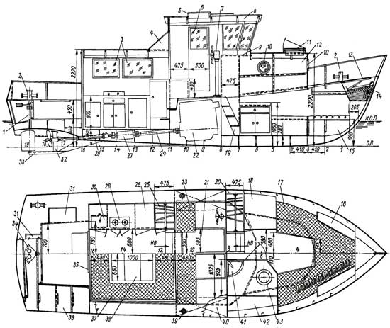
The general location of the boat in the style of a tugboat
zoom in, 1800x1204, 320 KB
1 — helmport, 60x3 pipe; 2 — cross bollard, 4 pcs.; 3 — portholes, plexiglass δ=5-8 mm; 4 — casing over a similar ladder; plywood δ=6 mm; 5 — sliding hatch in the roof of the wheelhouse; 6 — sliding door; 7 — steering wheel; 8 — cabin roof, plywood δ=6-8 mm, 9 — map table; 10 — round porthole; 11 — light hatch, plexiglass δ=5-8 mm; 12 — cockpit, welded steel structure δ=2 mm; 13 — hatch cover in the anchor niche; 14 — anchor with rope; 15 — locker; 16 — shelf for personal belongings; 17 — bunk, locker at the bottom; 18 — table with drawers; 19 — ladder; 20 — wardrobe; 21 — hatch cover to the engine compartment, light alloy; 22 — tractor diesel «Belarus»; 23 — steering seat; 24 — intermediate shaft, pipe 60x3; 25 — wardrobe; 26 — galley table, a provision cabinet or refrigerator at the bottom; 27 — reverse gear; 28 — gas stove; 29 — deadwood pipe; 30 — sink; 31 — hatch to the afterpick; 32 — two-legged propeller shaft bracket; 33 — protective spur; 34 — rudder sector; 35 — sliding door; 36 — afterpick; 37 — sofa folding into a double bed; 38 — folding table; 39 — filler neck of the fuel tank; 40 — fuel tank with a capacity of 300 liters; 41 — washbasin; 42 — shelf; 43 — pumping toilet (or portable bucket).
Theoretical drawing of the boat hull
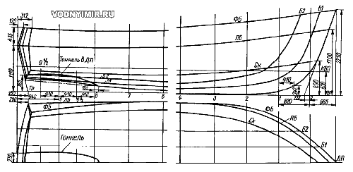
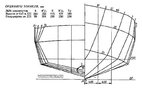
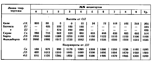
Table of plaz ordinates
Let's not be mistaken if we say that the main problem in this case is the engine (diesel) and its installation on the boat. The fact is that the domestic industry in the power range of 60-80 hp produces only one model of diesel in the marine version — a 6-cylinder 6CHSP 9.5/11. This engine is fully ready for installation on the boat: it is equipped with a reverse gearbox, a closed cooling system with water-water and water-oil refrigerators. However, due to the low speed of the crankshaft (1800 rpm), the engine has a rather large mass (580 kg) and dimensions that require an engine compartment of considerable length and height.
Engines produced abroad of the same power at a crankshaft speed of 2500-3000 rpm weigh 100-300 kg less, and most importantly, they have a significantly smaller overall length and height. In addition, 6CHSP 9.5 /11 diesels are produced in a small series, and therefore are difficult to access and very expensive. Domestic water-cooled tractor engines from MTZ Belarus tractors are more acceptable in size, more reliable and more affordable. Having served their time on tractors, these diesels are restored by amateurs and adapted to work on boats. The main issues of their application on small vessels can be found in the article by B. Sinilshchikov, published in «Boats and Yachts» No. 146, as well as in the book «Automobile engine on a boat», L., «Shipbuilding», 1980, written by him in collaboration with Yu. Mukhin.
The most complex node that needs to be manufactured independently is the reverse gear. The mentioned book provides a design diagram of such a device, which is installed separately from the engine and in this case is convenient: it can be placed under the cabin floor by connecting an intermediate shaft with elastic couplings to the engine. The installation of a diesel engine near the middle of the boat has a positive effect on its alignment, given the relative speed Fg = 0.65 — about 22 km/h, which a boat with an engine from Belarus can develop with its operating power of about 75 hp. Fuel tanks can also be located next to the engine — fuel consumption from them will practically not affect the trim of the vessel. The engine can be installed below deck in the area of the wheelhouse, and access to it can be provided through a hatch in the deck and removable shields or doors in the engine compartment bulkheads.
Only after making sure of the reality of the adaptation of the engine for the boat and the possibility of performing the necessary work for this, you can start building a boat.
Given the shallow waters of our inland waters and the lack of well-maintained berths, it is recommended to provide a shallow propeller tunnel in the aft part of the boat's bottom, which will reduce the overall draft of the boat by about 200 mm. The welded spur, fixed to the hull at the screw installation site, will serve as a support for the balance pen of the rudder and the foot of the propeller shaft bracket, and will also protect the screw and rudder when the boat is stranded.
The hull of the boat can be made of ordinary carbon steel grades St. 3, St. 4, or of high-quality structural steel St. 15. It is important that the builder does not come across steel with the index «kp» — «boiling», which is prone to cracking during welding. It is best to use steel with the index «sp» — «calm», which undergoes complete deoxidation during smelting. If the steel grade is unknown, it is advisable to check its mechanical properties in the laboratory. The yield strength of the material must be at least 2400 kg/cm²; the steel should have such plasticity that a strip with a thickness of Z mm could be bent 180° around a mandrel with a diameter of 1.5 mm without cracking. At least visual tests are desirable to subject samples of welds — butt and corner joints.
For the construction of the hull, about 600 kg of sheet steel with a thickness of Z mm will be needed, which will go to the outer skin and deck flooring. 100 kg of a 2.5 mm thick sheet (flora, knits, coamings, etc.) and about 450 kg of a two-millimeter sheet necessary for the manufacture of bulwarks, bulkheads, cutting of the bow forecastle, etc. It is necessary to think in advance about how the blanks will be cut — with a gas cutter, on mechanical scissors or guillotine. It may be necessary to resort to the services of a metalworking production or a cooperative. It will facilitate the work and the ability to use a flange bending machine designed for a metal thickness of up to 2.5 mm.
It is not recommended to reduce the thickness of the outer skin — you will have to complicate the set of the hull, introduce into the design elements such as squares or a round rod in the connection of the sheets along the cheekbone and the sides with the deck, the joints inside. And it will still be difficult to weld a high-quality housing from thin metal, in which there would be no residual deformations after welding — buckets and «houses». It usually takes a lot of work to edit them.
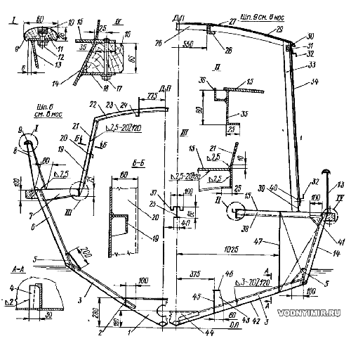
Cross-sections of the housing according to structural frames
zoom in, 1270x1457, 113 KB
The hull is recruited according to a transverse recruitment system, the main links of which are frames installed through 410 mm and transverse bulkheads. For frames, it is best to use a special shipbuilding profile — a half-bulb No. 6 (its height is 60 mm, the width of the bulb is 19 mm, the wall thickness is 5 mm). It is also possible to assemble frames from an uneven square of 5x36x56 mm or another, which, together with the attached belt of the outer skin, gives the same moment of resistance as the half-bulb. A half-bulb will require 100 linear meters or 210 kg. The longitudinal set consists of welded T-beams of the foundation for the engine, which in the bow and aft part pass into the bottom stringers, which serve as a support for the payoles. In the nose, the sheathing sheets are connected to the stem bent from a half-barrel No. 8 or a strip of 6x80 mm.
To facilitate the boat, the cabin cabin and steering room are provided with a wooden structure made of plywood with a thickness of 8-12 mm and pine slats. The walls of the cabins and racks are bolted to the steel coaming welded to the side formwork. A 100 mm high coaming serves as a threshold against the penetration of water into the boat.
The hull plating can be carried out according to a set — frame frames, bulkheads, transom and stem, mounted on the slipway in the up position with the keel or in the normal position. The second option is more convenient for welding, but presents difficulties for loosening the frame frames on the slipway, for which it is necessary to install upper slipway connections from rigid longitudinal beams (it is possible in the form of wooden beams).
Installation of the skin begins with the side sheets. The joints should be positioned no further than 100 mm from the nearest frame in order to reduce warping during welding. Having pressed the sheet to the set with the help of clamps, it is grabbed by electric welding to the frames and edges of the adjacent sheet. Then, also on the electric hooks, the sheets of the bottom lining are installed. When the entire skin is put in place, the frames and parts of the longitudinal set are welded with an intermittent checkerboard seam (welding length 20-25 mm, pitch — 120-150 mm) and at the end of this work, the grooves and joints of the outer skin are welded.
To perform this work, it is best to involve certified welders. The main seam is applied from the inside of the skin. Then the outside is cut down with a chisel and sandpaper is cleaned off all the welds from welding and the seam is carefully welded. Welding should be carried out simultaneously from both sides or alternately in sections of 0.7-1.0 m. All seams are sanded with sandpaper until the metal shines.
After welding the internal saturation parts and the longitudinal set, the waterproofness of the welds is checked. To do this, water is poured into the body to the level of 0.5 m above the cheekbone in the middle. Places of leakage are marked with chalk, after removing water from the body, the fistulas are cut and brewed. The waterproofness of the sides and bulkheads can be checked by watering them with water from hoses.
You can re-check the quality of the seams with kerosene. To do this, the seam from the outside is smeared with a thick solution of chalk in water. After the chalk dries, kerosene is applied to the seam from the inside with a brush. Cracks and imperfections in the seams are detected by oil stains protruding on the chalk coating. A known difficulty can be caused by welding a thin bulwark to the deck. This should be done with an intermittent seam, trying not to allow excessive heating of the lower edge of the sheet over a long length.
Special care is necessary when welding a deadwood pipe into the body, the axis of which must be aligned with the pre-punched shaft line, as well as when welding all seams of fuel tanks. After checking the density of the seams «for kerosene», the tanks should be filled with a solarium and make sure that there is no fuel filtration. Checking in bulk with water often does not reveal microcracks in the seams.
But the construction of the boat is far from complete with the manufacture of the hull. Experience shows that about 30% of the labor intensity and funds are spent on it. Ahead of the most difficult work on the equipment of the premises, installation of the engine and its maintenance systems, steering gear, etc., etc.
Boat projects for self-construction
Share this page in the social. networks or bookmark:
